

Why a fouled exchanger is a different exchanger
A heat exchanger is selected on a clean surface and then operated on a dirty one. The gap between those two states is the fouling allowance, and it is the least examined number in most specifications — usually inherited from a previous project, or copied from a table without asking what fluid the table was written for.
The allowance matters because it is not a small correction. On a clean duty the plate wall and the two convection films carry the heat. Add a deposit and you insert a third resistance in series, one that grows with time and that nothing in the unit controls. If that resistance is guessed too low, the unit commissions clean and then quietly fails to meet duty after the first season. If it is guessed too high, you pay for area you never use and, as described below, you may make the fouling worse.
What the fouling resistance actually does to the calculation
The overall heat transfer coefficient is built from resistances in series:
1/U = 1/α_hot + 1/α_cold + t/k + R_f,hot + R_f,cold
where the first two terms are the convection films, the third is the plate wall, and the last two are the fouling resistances on each side. Because the terms add as reciprocals, the smallest term dominates the result. In a clean plate heat exchanger the convection films are deliberately strong — that is the point of the corrugation — so the wall resistance is small and the overall coefficient is high. Insert a fouling resistance of the same order as the film resistance and U can drop by a third or more, even though the deposit is fractions of a millimetre thick.
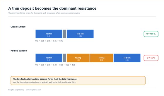
The consequence for the duty is direct. Required area is proportional to 1/U for a given temperature driving force, so a 30 % fall in U means roughly 40 % more area is needed than the clean calculation indicated. That is the allowance. It is not a contingency added at the end; it belongs inside the thermal calculation from the first iteration.
Typical fouling resistances by fluid
The values below are indicative ranges taken from published practice for conventional shell-and-tube design. They are a starting point for a plate unit, not a substitute for fluid data — and on plate units the effective values are often lower than the tubular figures because the higher wall shear keeps surfaces cleaner. Treat them as an order of magnitude, then confirm.
| Fluid / service | Typical Rf (m2·K/W) | What drives it |
|---|---|---|
| Clean river or lake water | 0.0002 – 0.0004 | Suspended solids, seasonal organics |
| Treated cooling tower water | 0.0002 – 0.0004 | Scaling, biological growth |
| Sea water | 0.0001 – 0.0002 | Biofouling more than scaling |
| Brine (secondary refrigerant) | 0.0002 – 0.0003 | Corrosion products, air ingress |
| Clean steam | 0.0001 | Essentially clean if dry and uncontaminated |
| Heavy fuel oil | 0.0007 – 0.0010 | Asphaltene and coke deposition |
| Hot heat transfer oil | 0.0003 – 0.0005 | Thermal degradation products |
| Dairy / food product | 0.0001 – 0.0003 | Protein denaturation at the hot surface |
| Untreated well water | 0.0004 – 0.0009 | Hardness, iron, silica |
Two cautions on using a table like this. First, fouling is a function of surface temperature as much as fluid: a protein stream that is innocent at 60 °C will deposit stubbornly at 85 °C, so the same fluid can need different allowances in different parts of the same plant. Second, the numbers were derived for tubular geometry. In a narrow plate channel the wall shear is higher, which suppresses deposit formation — but the same narrow channel is far less tolerant of the deposit once it forms. Both effects are real, and they push in opposite directions.
Why plate units are more sensitive to fouling than shell-and-tube
The hydraulic diameter of a plate channel is typically a few millimetres. A deposit 0.2 mm thick removes a meaningful fraction of the free cross-section, raises the pressure drop at constant flow, and if the pump curve is fixed, reduces the flow — which reduces the shear that was keeping the surface clean. Fouling in a plate pack therefore has a feedback loop that a large-diameter tube does not.
The same geometry that gives high coefficients also concentrates the penalty. Because the clean U is high, the fouling resistance represents a larger proportion of the total resistance than it would in a low-U tubular unit handling the same fluids. A plate exchanger can therefore lose a greater share of its performance to the same physical deposit.
The trade-off: margin versus velocity
Here is the part that surprises people. Adding area to cover fouling is not free, and it can be counter-productive.
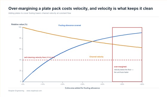
Area is added by adding plates. At constant flow, more plates mean more parallel channels, which means lower velocity per channel, which means lower wall shear. Below roughly 0.3–0.5 m/s in water service, deposition starts to outrun removal and the surface fouls faster than it would have at design velocity. The oversized unit then loses its margin sooner than the correctly sized one, and the operator concludes that the exchanger "fouls badly" when in fact it was designed with too much enthusiasm.
This is why the allowance should be sized to a realistic fouling resistance rather than to a feeling of safety, and why the resulting velocity should be checked afterwards. A useful discipline is to compute the unit twice: once with the expected fouling resistance and once clean, and confirm that the fouled case still sits above the minimum velocity for the service. If it does not, the answer is a different channel geometry, not more plates.
When the right answer is a wider channel, not more area
For streams with fibres, pulp, crystals, large particles or a strong scaling tendency, no amount of thermal margin solves the problem, because the failure mode is blockage rather than loss of coefficient. In those duties a wide-gap channel — larger plate spacing, free-flow ports, no contact points in the flow path — carries the same duty at a lower coefficient but keeps running. The selection criterion shifts from "how much area" to "what gap can pass the solids and be cleaned".
Recognising this early saves a redesign. If the fluid has a settling velocity, a fibre content, or a history of blocking other exchangers, the channel decision comes before the thermal calculation.
Setting the allowance on a real project
- Get the fluid data. Analysis for hardness, suspended solids, iron, silica, chloride and organics on both sides. An allowance guessed from a fluid name is a guess.
- Identify the hot surface. The side with the highest wall temperature fouls first. On a steam heater that is the process side, not the steam side.
- Choose Rf and compute the fouled U. Use the table as a sanity check, not as the input.
- Size the unit on the fouled case and check the clean case for over-velocity and control authority. The unit must be acceptable at both ends.
- Check the velocity. If the fouled case falls below the service minimum, change geometry rather than adding plates.
- Write the cleaning interval into the specification. An allowance assumes a maintenance regime. State what it is, so the assumption is visible to whoever operates the plant.
- Decide whether the duty needs a margin at all, or whether monitoring plus cleaning is the cheaper route. For a duty that runs a few weeks a year, cleaning twice is often cheaper than 40 % more area.
Common questions
Should the fouling allowance be added to the area or to the U value? To the resistance, which amounts to reducing U. Adding a percentage to the area at the end is a rough approximation that misbehaves when the two sides foul unequally.
Can a plate heat exchanger be cleaned well enough to restore the clean U? In most cases yes, if the deposit is removed fully and the gaskets are sound. Irreversible loss of performance usually points to corrosion or to deposit in the port area rather than on the plates.
Do I need the same allowance on both sides? No. Each side has its own fluid and its own wall temperature. Applying the worst case to both sides double-counts and produces an unnecessarily large unit.
Is a higher fouling allowance ever a safety requirement? It can be, where the consequence of not meeting duty is unacceptable and cleaning access is difficult. In that case the margin should be deliberate and documented, with the velocity penalty checked — not a default 20 % added to every project.
The short version
Fouling allowance is a thermal resistance, not a contingency. It belongs in the calculation, it should be derived from fluid data on each side, and it has a cost in velocity that is easy to overlook. The units that perform well over their life are usually the ones where the allowance was chosen deliberately and the cleaning regime was written down at the same time.
Reapter supplies gasketed plate heat exchangers, wide-gap units for fibrous and particulate streams, and plate-and-shell constructions for duties where gaskets are the weak point. Send us the fluid analysis and the duty, and we will size the unit on the fouled case and tell you plainly if the answer is a wider channel rather than more plates.
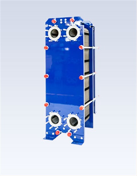 Food grade plate heat exchanger
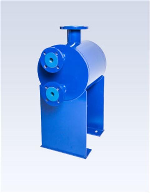 Plate And Shell Heat Exchanger