Variable Flow and Part-Load Operation of Plate Heat Exchangers

Part load is a different machine, not a smaller one
Most gasketed plate heat exchangers are selected at one point and then operated everywhere else. The selection point is a summer design day, a full production rate, a peak district heating morning. The other nine thousand hours of the year happen at 60%, 40%, sometimes 15% of that flow — and the unit does not simply perform at 60% of its duty. Its heat transfer coefficient falls, its pressure drop collapses, its channel velocities drop below the range that keeps the plates clean, and its control loop starts to hunt.
None of that is a defect. It is the consequence of how a plate pack works: narrow channels, turbulent flow, and a heat transfer coefficient that is a strong function of velocity. Understanding the shape of that curve is what separates a plant that modulates smoothly from one that cycles, fouls and is blamed on the exchanger.
Why the plate pack gains effectiveness as flow falls
In a plate heat exchanger the flow is fully turbulent at velocities where a shell and tube unit would still be in transition, which is why plate units reach high coefficients in a small footprint. The price is dependence. Over the normal operating band the single-phase coefficient follows roughly U proportional to velocity raised to about 0.7 — a little less for wide-gap and viscous duties, a little more for high-efficiency corrugations.
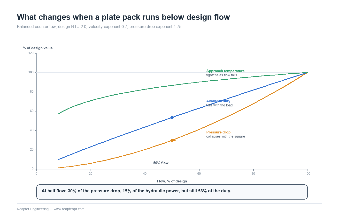
Cut both flows to half and the coefficient falls to roughly 62% of design. That sounds like a loss, and in one sense it is: the same plates now transfer less heat per kelvin of driving force. But the heat capacity rate has fallen by half, and it fell faster than the conductance. The number of transfer units — NTU, the ratio of conductance to capacity rate — therefore rises. For a balanced counterflow unit selected at NTU 2.0, halving the flow takes NTU to about 2.5 and effectiveness from 0.67 to 0.71.
So a plate heat exchanger at part load is not less effective. It is more effective and less powerful at the same time: the approach temperature between the two streams actually tightens, while the absolute duty available at fixed inlet temperatures falls to about half. That distinction matters, because the two common part-load complaints — "the outlet temperature will not hold" and "the approach is worse than design" — have completely different causes, and only the first one is a capacity problem.
The numbers between 100% and 20% flow
The table below is a worked example, not a universal law: balanced counterflow, design NTU 2.0, velocity exponent 0.7, pressure drop exponent 1.75, both streams reduced in proportion. Change the design NTU and the absolute values move; the shape of the trend does not.
| Flow (% of design) | Pressure drop | Duty at fixed inlet temperatures | Approach temperature |
|---|---|---|---|
| 100% | 100% | 100% | Design value |
| 75% | 61% | 77% | 6% tighter |
| 50% | 30% | 53% | 13% tighter |
| 30% | 12% | 33% | 22% tighter |
| 20% | 6% | 23% | 29% tighter |
Two practical readings follow. First, the energy argument for variable flow is real and it lives almost entirely in the pressure drop column: at half flow the hydraulic power absorbed by the pack is about 15% of design, because power scales as flow times pressure drop. Second, the exchanger is far more sensitive to flow than a control engineer expects. A 50% flow reduction removes nearly half the duty, so a control loop tuned at design conditions will overshoot every time the load steps down.
Where part-load operation actually goes wrong
Heat transfer is rarely the limiting factor. Three other things are.
- Flow distribution inside the pack. A plate channel is typically two to four millimetres deep. Distribution between channels depends on the inlet port and the corrugation geometry working in their intended velocity range; below roughly a quarter of design flow, the distribution pattern degrades and individual channels can run starved or stagnant while the pack average still looks acceptable. The symptom is a unit that passes its overall heat balance but develops local fouling or gasket failure in a band of plates.
- Velocity below the scour threshold. Design channel velocities usually sit somewhere in the 0.3 to 1.0 m/s band. Particulate streams need a minimum velocity to keep solids moving; drop below it for long enough and the unit behaves like a settling tank. Cooling water, river water, sea water and product streams with pulp or fibres are all in this category. Low flow does not cause fouling directly, but it removes the mechanism that was holding fouling back.
- Control instability. A two-way control valve sized for design flow has almost no authority at 20% flow, where the pack's pressure drop has fallen to a few percent of design and the valve is nearly closed. The result is hunting, and hunting means thermal cycling of the gaskets — the subject of the next section.
The bypass line is the exchanger's insurance
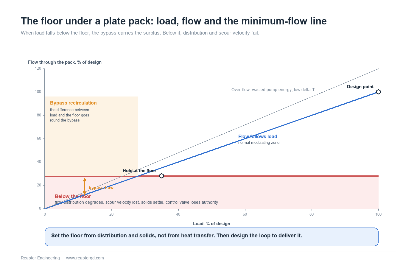
Variable primary flow is the standard architecture for district energy, chilled water and many process cooling loops, and it works well — but the loop has to include a path for the water that the load is not taking. On the source side, chillers and heat pumps have a minimum evaporator or condenser flow below which their own protection trips. On the exchanger side, the same minimum protects distribution and scour velocity.
Two arrangements are common. A decoupler or bypass pipe between supply and return headers keeps a minimum flow through the production equipment while the load takes what it needs. Alternatively a dedicated minimum-flow bypass with a modulating valve and a flow meter holds the pack above its floor. Either is acceptable; what is not acceptable is a design that relies on the load never dropping below 40%, because in a real building or plant it will.
Thermal cycling wears gaskets faster than low flow does
Elastomer gaskets fail by compression set and by movement. A unit that holds steady at 80 °C for years will usually outlast one that swings between 40 and 90 °C twice a day, because every swing works the gasket in its groove and every swing loads the plate pack differentially. Part-load operation is therefore a gasket life issue before it is a thermal one.
Three habits extend the life of a modulating unit. Keep ramp rates moderate — many operators set a limit of the order of one kelvin per minute on fluid temperature and avoid step changes above 20 to 30 K, with tighter limits on units with PTFE or compressed fibre gaskets. Avoid running the unit with one side cold and one side hot during start-up; bring both loops up together, or accept that the first minutes will put the pack through a thermal gradient it was not designed for. And do not let a control loop chase setpoint with full-stroke valve movements — a short stroke time and a properly sized valve are cheaper than a gasket set.
Proving part-load performance on site
Commissioning usually records one point at design flow, which tells you almost nothing about the other 90% of the operating year. A short part-load survey at three points — full flow, roughly half, and the minimum the control system will actually allow — is enough to separate a design problem from a fouling problem.
- Record flow, inlet and outlet temperature on both sides, pressure drop on both sides, and valve position at each point. Simultaneous readings only; a flow taken at 09:00 and a temperature at 09:20 describe two different machines.
- Compute the approach temperature and the actual UA at each point, and compare with the selection curve, not with a single design figure.
- If UA falls proportionally with the predicted part-load trend, the unit is clean and the design is behaving. If UA falls faster than the trend at low flow, suspect maldistribution or fouling in a band of channels.
- If the measured pressure drop at full flow is well above the curve, the first suspects are air in the pack, a closed valve somewhere, or a plate count higher than the drawing. Check the pack dimension before opening anything.
- Confirm the minimum flow actually delivered to the pack, not the minimum the control logic intends to deliver. A bypass valve that is stuck shut is invisible until a chiller trips.
Common questions
Does a plate heat exchanger lose efficiency at part load? Its heat transfer coefficient falls with velocity, roughly as velocity raised to 0.7, but its effectiveness usually rises because the capacity rate falls faster. The practical result is that the unit still approaches the temperatures well at low flow while its absolute duty falls with the load. Efficiency loss at part load is normally a pump and control problem, not a plate problem.
What is the minimum flow for a plate heat exchanger? There is no single number, because the limit is set by distribution and by the fouling behaviour of the stream rather than by heat transfer. Many selections remain well behaved down to about 25 to 30% of design flow on clean, low-solids duties; particulate or fibrous streams need a floor high enough to keep channel velocity above the scour threshold. Ask for the minimum in the selection report, and design the loop to respect it.
Why does the pressure drop fall so much when the flow is reduced? Because pressure drop in a turbulent channel scales with velocity to a power between about 1.7 and 2.0. Halving the flow cuts the pressure drop to roughly 30% of design, and the hydraulic power absorbed to about 15%. That is the whole economic case for variable flow — and also the reason a control valve sized at design conditions loses authority at low load.
Can a plate heat exchanger be started with cold water on one side? It can, within limits. A large step change in temperature puts the pack through a thermal gradient that loads the gaskets and the plate edges unevenly. Bring both loops up together where possible, respect the ramp limit, and avoid repeated cold starts against a hot pack — that is the cycling pattern that shortens gasket life most.
Does variable flow change the fouling rate? It can, in both directions. Higher sustained velocity at design flow resists deposition; long periods below the scour threshold allow it. A loop that spends most of its hours at 30% flow should be reviewed for cleaning interval on operating hours rather than calendar time.
Conclusion
Part-load behaviour is decided at the selection stage and paid for in operation. A unit with a documented part-load curve, a stated minimum flow and a loop that actually delivers that minimum will modulate quietly for years; a unit selected only at the design point will be judged on the hours nobody designed for. Reapter supplies gasketed, semi-welded and brazed plate heat exchangers for district energy, marine, HVAC and process cooling duties, with selection reports that carry part-load behaviour and minimum flow alongside the design point, and with engineering support for the control and bypass arrangements that keep the pack inside its operating envelope. If you are reviewing an existing loop, or specifying a new one, send us the duty range and the control philosophy and we will return the part-load curves with the quotation.
Related information
- Double-wall plate heat exchanger can ensure safe heat exchange equipment without cross contamination
- Qingdao Ruipute wide flow channel plate heat exchanger processing customization
- Plate sterilizer supporting plate heat exchanger and the difference between ordinary heat exchanger, do you understand?
- An article to take you to understand the structure of pharmaceutical and chemical plate heat exchanger and heat transfer
- Qingdao Ruipute, which is a plate heat exchanger factory that quality equals to GEA brand
- Look here to teach you the process of plate heat exchanger
Relevant article
- Variable Flow and Part-Load Operation of Plate Heat Exchangers
- Factory Acceptance Testing of Plate Heat Exchangers: What to Witness
- Plate Heat Exchanger Spare Parts Strategy: Stocking Against Real Lead Times
- Plate Heat Exchangers for Seawater and Brine Cooling: Materials and Limits
- Cross-Plate Leakage in a Plate Heat Exchanger: Diagnose Before You Order Parts
- Hygienic Design for Food-Grade Plate Heat Exchangers: What the Standards Require
- Plate Heat Exchanger Flow Arrangement: Series, Parallel and Multi-pass
- Fouling Allowance in Plate Heat Exchanger Design: Sizing the Margin
- Close Temperature Approach in Plate Heat Exchangers: How Close Is Practical?
- District Heating Substations: Sizing Plate Heat Exchangers for Seasonal Load
Latest information
- The original lubricant in the chemical plate heat exchanger plays so many roles!
- Heat exchanger station supporting plate heat exchanger or have to pay attention to these points, or easily go wrong
- Heat station supporting plate heat exchanger installation is a technical work, these points should be noted
- Improve the efficiency of industrial boilers with plate heat exchanger, these maintenance points to keep in mind
- The Integrated Heat Exchanger Unit: An Efficient Integration and Intelligent Control Solution for Thermal Energy Conversion
- Sulfuric acid and other corrosive media for industrial plate heat exchanger requirements are what
- Simple and effective chemical cleaning method of coal chemical plate heat exchanger, can effectively improve efficiency
- A high-quality petrochemical plate heat exchanger in the production of what to consider
- These causes of chemical plate heat exchanger gasket aging you may not know
- Chemical plant plate heat exchanger, sulfuric acid cooling needs attention