Waste Heat Recovery with Plate Heat Exchangers: Sizing and Fouling

Waste heat is a temperature problem before it is an equipment problem
Most industrial sites do not lack waste heat — they lack waste heat at a temperature worth recovering. A cooling water loop returning at 32 °C contains a great deal of energy and almost none of it is useful for process heating; a compressor discharge at 85 °C contains far less total energy and can preheat a large volume of domestic hot water. The first question in any recovery project is therefore not which exchanger to buy but where on the temperature scale the heat sits, and what it can be exchanged against.
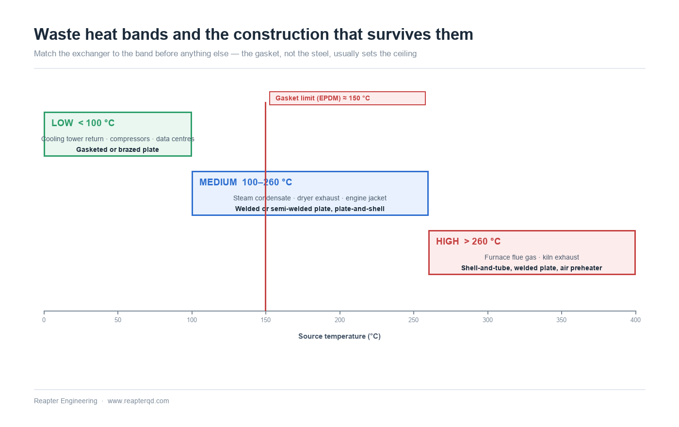
Plate heat exchangers are the default answer for liquid-to-liquid recovery in the low and medium bands, roughly from ambient up to about 150 °C. Above that, the gasket becomes the limiting component and the construction has to change. Below it, the limits are fouling, approach and economics — in that order.
Three temperature bands, three different answers
The classification below is a working one, not a standard. Its purpose is to map a heat source to the exchanger construction that can actually survive it.
| Band | Typical sources | Usual construction | Governing limit |
|---|---|---|---|
| High, above ~260 °C | Furnace flue gas, kiln exhaust, incinerator off-gas | Shell-and-tube, welded plate, air preheater | Material strength, creep, acid dew point |
| Medium, ~100–260 °C | Steam condensate, dryer exhaust, engine jacket water, process cooling | Welded or semi-welded plate, plate-and-shell | Gasket temperature limit, thermal expansion |
| Low, below ~100 °C | Cooling tower return, compressor cooling, chiller condensers, data centre loops | Gasketed or brazed plate | Approach, fouling, payback period |
The temperature ceiling for gasketed plate units is set by the elastomer, not by the stainless steel. EPDM is commonly rated to about 150 °C and NBR to roughly 110–120 °C in continuous service, with both figures falling as the fluid becomes more aggressive. Compressed fibre and PTFE gaskets extend the range at a cost in handling and in maintenance. Above the gasket limit, the choice is welded plate, plate-and-shell or a conventional shell-and-tube.
Pinch point: the number that decides whether the project works
In a recovery duty there are always three streams: the hot source, the cold sink, and the economics. The minimum temperature difference between hot and cold streams — the pinch — links all three. A tighter pinch recovers more heat but needs more area; a wider pinch is cheaper to build and recovers less.
What surprises people is how steeply the curve runs at small pinch values. Halving the pinch from 10 K to 5 K roughly doubles the required area for a given duty, and going from 5 K to 2 K roughly doubles it again. Plate exchangers make tight pinches affordable because their area per unit volume is high, which is precisely why they dominate low-grade recovery — but the curve still bends.
The practical rule is to set the pinch from the value of the recovered energy, not from what the exchanger can achieve. If the site runs 6,000 hours a year and the recovered heat displaces purchased steam, a 3 K pinch is usually justified. If the site runs 800 hours a year on an intermittent process, a 10 K pinch with a cheaper exchanger is the better investment.
The dirty side decides the design
Recovery duties are dirtier than clean process duties by nature. The heat is often in a stream that nobody was treating because nobody cared about it — cooling tower water with biological growth, quench water with suspended solids, compressor cooling water with iron oxide, effluent with fibre. Once that stream enters a plate pack with 2–3 mm channels, the fouling that was harmless in a large pipe becomes a blockage.
Three design responses matter here. Wide-gap plates, with channel spacing of 6–12 mm instead of the usual 2–4 mm, pass particulate without bridging and are cleanable in place. Asymmetric plate patterns allow the dirty side to run in the wide channel while the clean side keeps a high heat transfer coefficient in the narrow one — the correct arrangement for almost every recovery duty, and a significant improvement over a symmetric plate pack. And a gasketed rather than brazed unit allows mechanical cleaning when chemical cleaning is not enough.
Where the source stream is genuinely fibrous or contains large solids, a plate exchanger is the wrong tool and a wide-gap or shell-and-tube unit should be considered instead. Choosing plate construction for a duty it cannot be cleaned in is the most common failure mode in recovery projects. Our article on sizing the fouling allowance covers how much margin to carry.
Acid dew point: where recovery stops being free
Flue gas recovery has a hard floor that has nothing to do with exchanger performance. Combustion gas containing sulphur trioxide forms sulphuric acid when it cools below the acid dew point, typically somewhere between 120 °C and 160 °C depending on sulphur content, excess air and water vapour. Cool the metal wall below that temperature and the exchanger becomes a corrosion test rig.
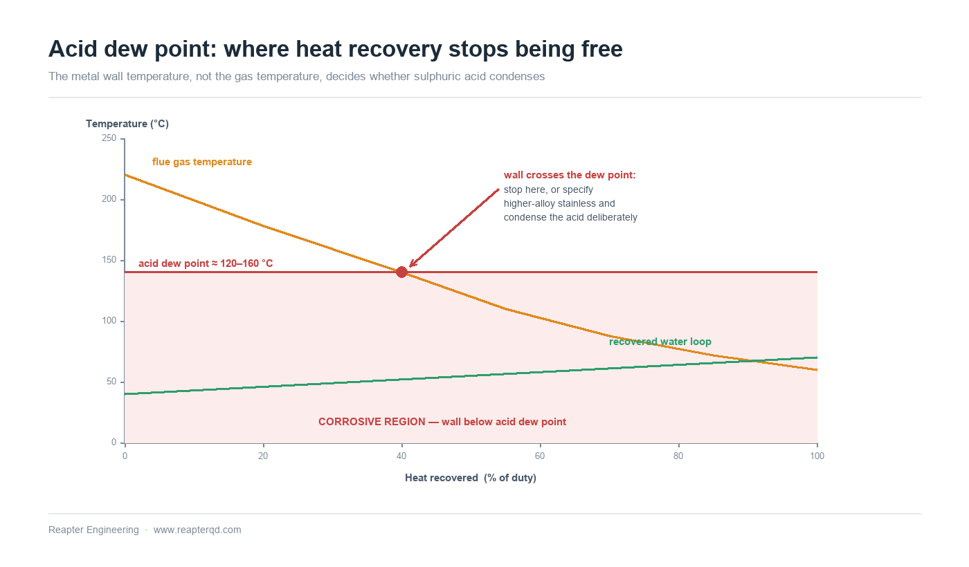
Two strategies exist. The conventional one keeps the cold-side inlet temperature high enough that the wall never drops below the dew point, which caps the recovery at the sensible heat above that temperature. The alternative deliberately condenses the acid and uses corrosion-resistant materials — higher-alloy stainless, or in severe cases fluoropolymer-coated surfaces — to recover the latent heat as well. The second recovers substantially more energy and costs substantially more; it is worth doing when the fuel is expensive and the operating hours are high, and not otherwise.
The same logic applies to any stream with a condensable acid component, and to streams that can deposit solids when they cool. In all of them, the minimum metal temperature — not the minimum fluid temperature — is the design constraint.
The three numbers that decide payback
Recovery projects fail on economics far more often than on engineering. Three inputs determine whether a scheme pays:
- Duty actually recovered. Not the theoretical maximum, but the duty at the pinch chosen and at the flows the plant really runs. A exchanger sized for a peak flow that occurs two weeks a year is a capital cost with no return.
- Equivalent operating hours. The single most commonly overstated figure in a payback calculation. Batch plants, seasonal processes and sites with frequent shutdowns often run 2,000–3,000 equivalent full-load hours, not 8,000.
- Value of the displaced energy. Steam, gas, electricity and chilled water are not interchangeable, and the marginal cost is not the average cost. Displacing purchased steam at the margin is worth far more than reducing a boiler's load below its baseline.
A useful discipline is to compute payback with the pessimistically low number for each of the three, and only proceed if the project still works. If it only works with all three optimistic, the engineering is not the problem.
Configurations that recur
Most industrial recovery schemes fall into a small number of patterns:
- Compressor jacket and oil cooling to domestic hot water. Medium band, clean streams, gasketed or brazed plate. Usually the fastest payback on site.
- Cooling tower return to process preheat. Low band, dirty stream on one side, asymmetric wide-gap plate on the tower side.
- Boiler blowdown to make-up water. Small duty, very high value because the displaced energy is at steam temperature; the constraint is often the blowdown flash rather than the exchanger.
- Condensate subcooling. Recovers sensible heat below the steam temperature without affecting the steam header; a compact plate duty with excellent economics.
- Data centre or chiller loop to district heating. Low band, large flows, and increasingly common as a way to make a cooling load into a revenue stream.
A selection sequence
- Measure the source first. Flow, temperature and variability over a full production cycle. A recovered duty based on a design figure that the plant never reaches is a wasted exchanger.
- Place the duty in its temperature band and check the gasket or material limit before anything else.
- Choose the pinch from operating hours and energy value, not from the best area the exchanger can achieve.
- Characterize the dirty side — particulate size, fibre content, scaling tendency — and select wide-gap or asymmetric channels accordingly.
- Check the minimum wall temperature against any acid or salt dew point, and decide whether to stay above it or specify corrosion resistance and condense.
- Confirm cleanability: can the unit be opened, and is there physical space and a drain for cleaning?
- Run the payback pessimistically before committing to the plate area.
Common questions
What is the minimum temperature difference worth recovering? There is no fixed number, but below about 5 K the required area rises steeply and the project usually only makes sense with very high operating hours. Between 5 K and 15 K most industrial schemes land.
Can a plate heat exchanger handle flue gas? Directly, rarely — plate units are liquid-to-liquid devices, and flue gas recovery normally uses a separate loop or an air preheater. Where a liquid intermediate loop is used, the plate exchanger on the liquid side is straightforward; the acid dew point limit applies to the gas-side exchanger.
Why wide-gap plates rather than a bigger conventional unit? Because fouling is a function of channel spacing, not of total area. A larger unit with narrow channels fouls at the same rate and simply takes longer to block. Wide-gap channels pass the particulate and can be cleaned.
How much fouling margin should be added? It depends on the stream, but typical values run from 10 % for clean cooling water to 25 % or more for effluent and fibrous streams. Our article on fouling allowance sets out how to size the margin rather than guess it.
Is recovery worth it if the site only runs seasonally? Usually not for low-grade heat, because the capital has too few hours to amortize against. It can still be worth it for high-temperature duties where the displaced energy is expensive.
Conclusion
Waste heat recovery pays when the temperature band is right, the pinch is set from economics rather than ambition, and the dirty side is designed for the fouling it will actually see. Most failed projects get one of those three wrong, and usually it is the third.
Reapter supplies gasketed, wide-gap and welded plate heat exchangers for recovery duties across the low and medium bands, with asymmetric channel arrangements where one side is dirty. If you have a stream you are currently rejecting, send us the flow, the temperature profile and the fouling behaviour — we will tell you what is recoverable and what the exchanger needs to look like. Ask for a recovery assessment.
Related information
- Still worry about the heat transfer condition with large particles and high viscosity? GEA free flow plate heat exchanger for you
- Causes of heat exchanger gasket aging
- What are the differences between the equipment produced by a plate heat exchanger specialized processing plant?
- The actual capacity of net celebrity milk tea does not match the content. The plate heat exchanger manufacturer said: We never cut corners!
- Industrial plate heat exchangers in niche markets
- A 20-kilometer heating pipe network is newly laid in Chengyang District, Qingdao, and plate heat exchangers will make the winter of 2020 warmer
Relevant article
- Reading a Water Analysis Before You Specify a Plate Heat Exchanger
- High-Temperature Heat Pumps Above 100 °C: Exchanger Selection for Steam Replacement
- Data Centre Waste Heat to District Heating: Matching Low-Grade Heat to a Network
- Plate Heat Exchanger Sizing: A Worked Calculation from Duty to Plate Count
- Plate Heat Exchanger Troubleshooting: Reading the Symptoms Before Opening the Pack
- Winter Shutdown and Freeze Protection for Plate Heat Exchangers
- Transcritical CO2 Systems: Selecting Plate Heat Exchangers for High Pressure
- Waste Heat Recovery with Plate Heat Exchangers: Sizing and Fouling
- Plate Heat Exchangers in Heat Pump Systems: Source-Side and Load-Side Selection
- Plate Heat Exchangers in Data Center Liquid Cooling: CDU Selection
Latest information
- The original lubricant in the chemical plate heat exchanger plays so many roles!
- Heat exchanger station supporting plate heat exchanger or have to pay attention to these points, or easily go wrong
- Heat station supporting plate heat exchanger installation is a technical work, these points should be noted
- Improve the efficiency of industrial boilers with plate heat exchanger, these maintenance points to keep in mind
- The Integrated Heat Exchanger Unit: An Efficient Integration and Intelligent Control Solution for Thermal Energy Conversion
- Sulfuric acid and other corrosive media for industrial plate heat exchanger requirements are what
- Simple and effective chemical cleaning method of coal chemical plate heat exchanger, can effectively improve efficiency
- A high-quality petrochemical plate heat exchanger in the production of what to consider
- These causes of chemical plate heat exchanger gasket aging you may not know
- Chemical plant plate heat exchanger, sulfuric acid cooling needs attention