Plate Heat Exchanger Sizing: A Worked Calculation from Duty to Plate Count

A sizing sheet is a sequence, not a formula
Most plate heat exchanger sizing goes wrong before any arithmetic starts. The engineer picks a U-value from memory, divides the duty by it, adds "20 % for fouling", and arrives at an area. The number looks defensible and is often 30 % away from what the unit will actually do — because the sequence was wrong, not the maths.
The order matters: fix the duty, choose the flow arrangement, then let the arrangement set the velocity, and only then let the velocity set U. Run it the other way round and every downstream number inherits the guess. What follows is the six-step sequence we use, worked through on a 500 kW water-to-water case, with the numbers left visible so you can check them against your own duty.
Step 1: Fix the duty, then let temperatures follow
A duty is four temperatures and two flows. In practice two of those are given and two must be chosen, and the choice is a process decision rather than a heat exchanger decision. For a water-to-water duty the heat load is:
Q = ? · cp · ΔT where Q is in kW, ? in kg/s, cp ≈ 4.19 kJ/kg·K for water, ΔT in K.
What people get wrong here is treating the secondary flow as free. It is not: flow sets the velocity inside the plate channels, velocity sets both the heat transfer coefficient and the pressure drop, and pressure drop is usually the constraint that decides the plate size. A duty specified with unlimited flow will select a small, cheap exchanger that cannot be run on the pump actually installed.
Two rules that prevent most of the trouble:
- Write the allowable pressure drop for both sides into the specification, before selection. 30–50 kPa is common for clean water; 50–80 kPa is normal where a close approach is required; below 20 kPa you are usually buying area.
- State the fluid as it will be, not as it is at commissioning. Glycol concentration, suspended solids and fouling tendency all change U and pressure drop, and the exchanger must be selected on the worst of them.
Step 2: Choose the flow arrangement before the plate
Counter-current single-pass is the default, and for good reason: it produces the highest correction factor and the most even velocity distribution. Series and parallel arrangements exist to solve specific problems — too little flow for a stable velocity, or too much pressure drop for the pump — and both of them cost you mean temperature difference. Choose the arrangement first, because it changes the F factor in Step 4 and the channel count in Step 5.
The trade is set out in detail in series, parallel and multi-pass arrangements; for sizing purposes the only thing to carry forward is that a multi-pass arrangement will reduce F and therefore increase area for the same duty.
Step 3: Estimate U from the fluids, then verify it
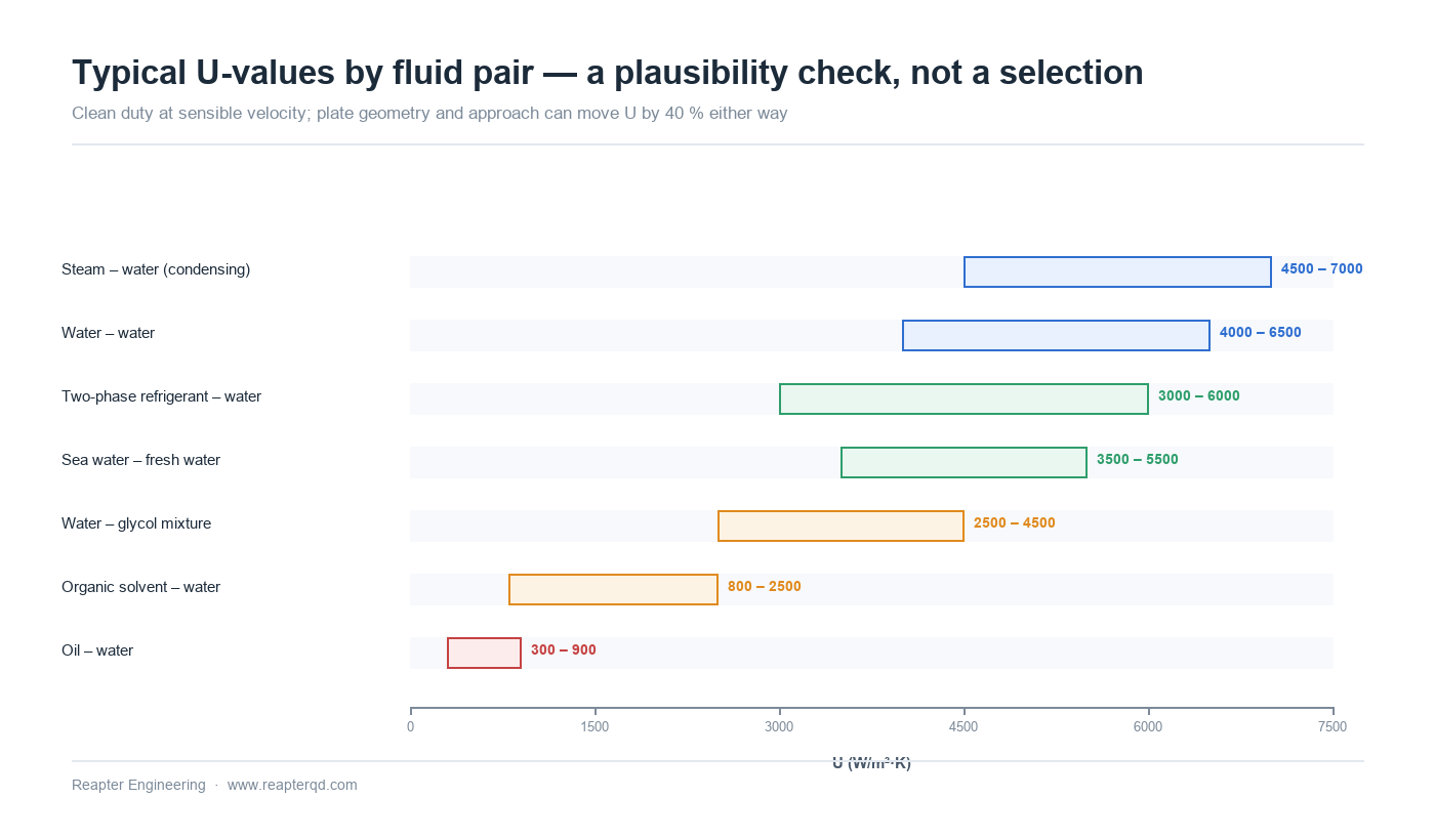
U is an output, not an input. But selection has to start somewhere, so start with a range matched to the fluid pair and then check it against the resulting velocity. If the velocity implied by your U is outside 0.3–1.0 m/s for water, the U is suspect.
| Fluid pair | Typical U (W/m2·K) | Notes |
|---|---|---|
| Water – water | 4 000 – 6 500 | Falls toward the low end as the approach tightens and velocity drops |
| Water – water, glycol mixture | 2 500 – 4 500 | Depends strongly on concentration; 50 % glycol can cost 35 % of U |
| Steam – water (condensing) | 4 500 – 7 000 | Very high on the condensing side; the water side usually controls |
| Organic solvent – water | 800 – 2 500 | Viscosity-driven; check at the cold end, not the mean |
| Oil – water | 300 – 900 | Often the oil side controls; velocity must stay high enough to limit fouling |
| Two-phase refrigerant – water | 3 000 – 6 000 | Maldistribution at part load is the real limit |
| Sea water – fresh water | 3 500 – 5 500 | Titanium plates; fouling margin matters more than U |
These ranges are for clean conditions at sensible velocities. They are not a substitute for a rated selection, and they should never appear on a purchase order. Their job is to tell you whether the area you are being offered is plausible.
Step 4: Correct the mean temperature difference
The log mean temperature difference is calculated from the two terminal differences:
LMTD = (ΔT1 ? ΔT2) / ln(ΔT1 / ΔT2)
with ΔT1 and ΔT2 taken at the two ends. For true counter-current flow this is the whole answer. For any real plate pack it is not, because the flow is not perfectly counter-current across the port and distribution regions. A correction factor F between 0.90 and 0.99 is normal for single-pass plate units; multi-pass arrangements and very unbalanced duties push it lower.
The correction is routinely omitted, and it flatters the design by 2–10 % of area. On a tight-approach duty that is the difference between meeting the guarantee and arguing about it.
Step 5: Turn area into plates
With duty, U, F and LMTD fixed, the required area is direct:
A = Q / (U · F · LMTD)
Then add the fouling allowance — as an area margin, not as a reduction in U, because the two are not equivalent when the fouling layer sits on one side only. A 10–20 % area margin is normal for clean water, more for open circuits, cooling tower water or any duty with a known scaling mechanism. The reasoning behind the margin is covered in sizing the fouling allowance.
Finally divide by the effective area per plate, and add the end plates. The result is a plate count, and plate counts are integers — always round up, and check that the resulting channel count still gives a velocity inside the acceptable band. If it does not, the plate size is wrong, not the count.
Worked example: 500 kW, water to water
Hot side 90 → 70 °C, cold side 35 → 60 °C, counter-current, clean water both sides, 50 kPa allowed on each side.
| Step | Quantity | Calculation | Result |
|---|---|---|---|
| 1 | Hot-side flow | 500 / (4.19 × 20) | 5.97 kg/s ≈ 21.5 m3/h |
| 1 | Cold-side flow | 500 / (4.19 × 25) | 4.78 kg/s ≈ 17.2 m3/h |
| 2 | Arrangement | Single-pass counter-current | No correction penalty |
| 3 | Assumed U | Water–water, ~0.5 m/s | 4 500 W/m2·K |
| 4 | Terminal differences | 90 ? 60 = 30 K; 70 ? 35 = 35 K | ΔT1 = 30, ΔT2 = 35 |
| 4 | LMTD | (35 ? 30) / ln(35/30) | 32.4 K |
| 4 | Correction F | P = 0.45, R = 0.80 | 0.95 |
| 5 | Clean area | 500 000 / (4 500 × 0.95 × 32.4) | 3.61 m2 |
| 5 | With 15 % margin | 3.61 × 1.15 | 4.15 m2 |
| 5 | Plates at 0.20 m2 each | 4.15 / 0.20 | 21 effective plates |
Twenty-one effective plates is the answer the arithmetic gives, and it is not yet an order. The selection still has to confirm that 21 plates with these flows lands inside the pressure drop budget — if pressure drop comes back at 85 kPa, the fix is a larger plate at a lower count, not a smaller one at a higher count. That check is why the selection is run in software rather than by hand; the hand calculation tells you what to expect and whether the offer in front of you is in the right region.
The five errors that survive review
Using arithmetic mean temperature difference. On the example above, AMTD is 32.5 K against a true LMTD of 32.4 K — close enough to hide. On unbalanced duties the error reaches 20 %, always in the direction of undersizing.
Applying the fouling margin to U instead of to area. A 15 % cut in U and a 15 % addition of area are not the same thing once the two sides foul at different rates, and only one of them is conservative.
Sizing at the rated point only. A unit that meets duty at design conditions but cannot at 60 % flow will be the subject of a complaint. Check the part-load point; the behaviour under variable flow is where most disappointing installations are decided.
Ignoring the pressure drop the pump can actually deliver. A selection that meets the thermal duty at 120 kPa is not a selection if the installed pump gives 60.
Treating the plate as a commodity. Two plates with the same outside dimensions can differ by 40 % in effective area and by a wider margin in chevron angle; the chevron angle alone shifts the U / pressure drop balance substantially. Area is not the specification — the rated performance is.
FAQ
Can I size a plate heat exchanger from a catalogue table alone? Only to check plausibility. Catalogue tables are generated at fixed conditions and fixed pressure drop allowances; your duty will differ on at least one of them.
What U should I use for a first estimate on glycol? Take the water value and expect 25–35 % less for a 30 % mixture, up to 45 % less at 50 %, depending on the operating temperature. Then confirm.
How much area margin is too much? Beyond about 25 % on a clean duty you are buying plates that will run at low velocity, which accelerates fouling and reduces the benefit you paid for. Margin is not free protection.
Why does the supplier's plate count differ from mine? Usually the U-value or the pressure drop allowance, sometimes the plate size. Ask for the rated U, the velocity per side and the pressure drop per side — the three numbers reconcile almost every discrepancy.
Let the duty run through the sequence
Reapter supplies gasketed, semi-welded, fully welded and plate-and-shell exchangers, and every selection starts from the six steps above rather than from a stock model. Send the four temperatures, both flows, the fluid as installed and the pressure drop available on each side, and we will return a rated selection with U, velocity and pressure drop per side shown — so you can check it against your own calculation rather than take it on trust. Request a sizing review.
Related information
- How can I buy a cost-effective plate heat exchanger?
- Temporary treatment for aging gasket plate heat exchanger
- Insiders tell you how to select and replace the gaskets of plate heat exchangers
- Water source conditions of plate heat exchanger
- Marine aquaculture plate heat exchangers have many functions, and people around this area are using them
- Application of imported plate heat exchanger in waste heat recovery of large particle medium production line
Relevant article
- Reading a Water Analysis Before You Specify a Plate Heat Exchanger
- High-Temperature Heat Pumps Above 100 °C: Exchanger Selection for Steam Replacement
- Data Centre Waste Heat to District Heating: Matching Low-Grade Heat to a Network
- Plate Heat Exchanger Sizing: A Worked Calculation from Duty to Plate Count
- Plate Heat Exchanger Troubleshooting: Reading the Symptoms Before Opening the Pack
- Winter Shutdown and Freeze Protection for Plate Heat Exchangers
- Transcritical CO2 Systems: Selecting Plate Heat Exchangers for High Pressure
- Waste Heat Recovery with Plate Heat Exchangers: Sizing and Fouling
- Plate Heat Exchangers in Heat Pump Systems: Source-Side and Load-Side Selection
- Plate Heat Exchangers in Data Center Liquid Cooling: CDU Selection
Latest information
- The original lubricant in the chemical plate heat exchanger plays so many roles!
- Heat exchanger station supporting plate heat exchanger or have to pay attention to these points, or easily go wrong
- Heat station supporting plate heat exchanger installation is a technical work, these points should be noted
- Improve the efficiency of industrial boilers with plate heat exchanger, these maintenance points to keep in mind
- The Integrated Heat Exchanger Unit: An Efficient Integration and Intelligent Control Solution for Thermal Energy Conversion
- Sulfuric acid and other corrosive media for industrial plate heat exchanger requirements are what
- Simple and effective chemical cleaning method of coal chemical plate heat exchanger, can effectively improve efficiency
- A high-quality petrochemical plate heat exchanger in the production of what to consider
- These causes of chemical plate heat exchanger gasket aging you may not know
- Chemical plant plate heat exchanger, sulfuric acid cooling needs attention