Plate Heat Exchangers in Data Center Liquid Cooling: CDU Selection

Liquid cooling efficiency is settled inside the CDU, at the plate pack
A coolant distribution unit is often described by its pump power and its control logic, but the number that decides how much cooling the facility actually has to buy is the approach temperature of the heat exchanger inside it. A CDU holding 1 K approach passes almost all of the secondary loop's heat to the facility water at a temperature close to the chip return temperature; a CDU holding 5 K forces the facility loop colder, which in turn reduces the hours per year that a dry cooler can carry the load without mechanical refrigeration.
That single number links the rack to the weather. As rack densities move from the 5–15 kW range that air cooling handles comfortably into the 60–120 kW range now common in accelerated computing, the plate heat exchanger inside the CDU becomes a first-order part of the facility design rather than an accessory.
The heat exchanger sits exactly at the isolation boundary
Liquid-cooled servers are served by a technology cooling system (TCS) loop — usually a mixture of water and glycol, or deionized water with inhibitors — that runs through cold plates on the processors. The facility water system (FWS) on the other side is the building's own loop, with its own water quality, its own treatment regime and its own operators. The two must exchange heat without exchanging fluid.
The plate heat exchanger in the CDU is that boundary. Everything about its specification follows from the fact that it is simultaneously a thermal component and a hydraulic firewall.
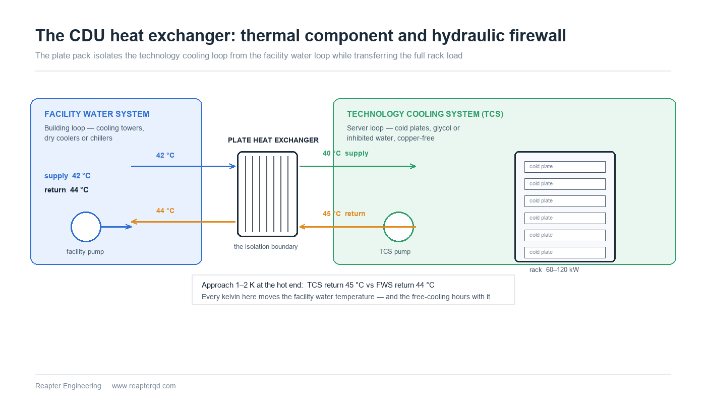
This is why CDU exchangers are almost always gasketed or semi-welded rather than brazed. A gasketed unit can be opened for inspection and mechanical cleaning, which matters because the TCS side is a closed loop that will accumulate whatever the cold plates shed over years of service. It also allows the plate pack to be re-configured if the rack load changes — a realistic event in a facility where a hall is refreshed every five to seven years.
Approach is the lever on PUE and on free cooling hours
Two effects follow from a wider approach, and they compound.
First, the facility water must be supplied colder for the same chip return temperature. If the TCS returns at 45 °C and the CDU holds 1 K approach, facility water enters at about 44 °C; at 5 K approach it must enter at 40 °C. Second, a lower facility water temperature reduces the number of hours a dry cooler can reject the heat passively, because the dry cooler's approach to ambient is what determines whether it can reach that temperature at all. In a temperate climate, 4 K of lost CDU approach can translate into several hundred extra hours of chiller operation a year.
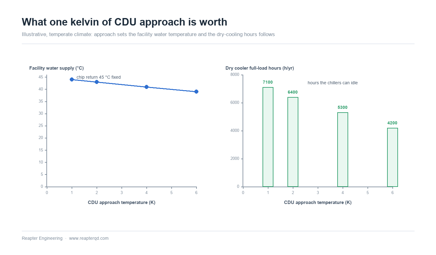
Plate exchangers reach 1–2 K approach comfortably on clean duties, which is why they are the default in this application rather than shell-and-tube or brazed alternatives. The constraint on going lower is not the plate pattern but the pressure drop budget: approach and pressure drop trade against each other through channel geometry, and in a CDU the pressure drop is paid twice — once by the facility pump, once by the pump that sits inside or beside the rack.
Secondary-side pressure drop is paid inside the rack
In an in-rack or in-row CDU, the TCS pump is part of the IT equipment's cooling system, not the building's. Its power counts against the rack's thermal overhead, and every kilowatt of pump power is a kilowatt that cannot be sold as compute. That changes the optimization: a CDU exchanger should be selected for the lowest pressure drop that still meets the approach target, not the highest effectiveness achievable.
Typical designs land in the 20–50 kPa range on the TCS side and somewhat higher on the facility side, where the pump is usually larger and the loop longer. Because TCS flow varies strongly with IT load — and flow-related pressure drop falls with the square of flow — the part-load behaviour is favourable, but only if the control valve and the pump curve allow flow to actually fall. A constant-flow TCS loop gives away most of that benefit.
One further constraint deserves mention: the plate pack must tolerate the transient when a rack is switched on. A sudden step in load produces a step in return temperature, and the exchanger sees a thermal shock that a brazed unit handles easily but a gasketed unit must be designed for — plate stiffness, gasket hardness and the frame's ability to absorb differential expansion all matter.
Water quality, aluminium cold plates and galvanic risk
The TCS loop is usually the more sensitive of the two, because it touches the servers. Aluminium cold plates are common, and aluminium in contact with copper or brass in the presence of an electrolyte is a galvanic couple that will consume the aluminium. This has a direct consequence for exchanger specification: no copper alloys on the TCS side, which means stainless plates and stainless or non-metallic connections rather than the copper-brazed construction common in HVAC duties.
Water quality follows the facility water categories used in data centre design — supply temperatures from roughly 17 °C to 45 °C, each with its own water quality expectations. Whatever category applies, the exchanger has to be compatible with the treatment regime actually used, not an idealized one: closed loops accumulate inhibitor breakdown products, and some inhibitors are aggressive to specific stainless grades at elevated temperature.
For chloride and alloy selection in cooling-water duties, our article on material selection from 316L to Hastelloy sets out the boundaries. In most CDU applications 316L is sufficient; the cases that need more are the ones with brackish or recycled facility water.
Cross-contamination: where double-wall construction earns its cost
The isolation between TCS and FWS is normally maintained by a single plate wall. That is acceptable in most facilities, but not in all. Where the facility water is of poor quality, where the TCS serves equipment with a contractual uptime guarantee, or where a leak from facility water into the server loop would be catastrophic rather than merely expensive, double-wall plates with a vented interspace are specified instead.
A double-wall plate has two separate walls with a gap between them, vented to atmosphere. A through-crack in either wall leaks to the vent rather than into the other circuit, and the leak is visibly detectable. The thermal penalty is real — the gap adds resistance — so double-wall units need more area for the same duty. The decision is a risk-transfer decision, and it should be made explicitly rather than by default.
Redundancy and part load
CDUs are usually configured N+1, which means the standby unit runs at low load or idle for most of its life and then has to take full load instantly when the lead unit is isolated. Two things follow for the exchanger: the plate pack must be sized for the full duty on the standby unit (not a fractional share), and the isolation valves must be arranged so that switching does not dead-head either loop.
Because a data hall's load profile is far flatter than a building's, part-load operation is less about seasonal variation and more about the long tail below design capacity that occurs in the first years of a facility's life. A CDU selected to its exact design point will run at 40–60 % of design flow for a considerable period, and the exchanger's performance at that flow — not at rated — is what the facility actually experiences.
Selection checklist for CDU heat exchangers
- Fix both loop temperatures at design and at the expected long-term part-load point. Chip return temperature, TCS supply temperature, facility water supply and return.
- Set the approach target first (1–2 K) and treat it as a facility-level decision, because it propagates into dry cooler sizing and chiller hours.
- Budget pressure drop separately for each side, and remember the TCS side is paid inside the rack.
- Confirm materials are copper-free on the TCS side if aluminium cold plates are used.
- Decide double-wall versus single-wall explicitly, based on facility water quality and the consequence of cross-contamination.
- Check the standby unit is sized for full duty, and that switching transients are within the exchanger's thermal shock tolerance.
- Require cleanability: a gasketed or semi-welded unit that can be opened, with documented gasket material compatible with the actual TCS fluid.
Common questions
What approach temperature should a CDU heat exchanger achieve? One to two kelvin is normal for plate construction and is where most well-specified units land. Above about 3 K the facility water has to be supplied noticeably colder, which costs free-cooling hours.
Why not use a brazed plate heat exchanger in a CDU? Brazed units are cheaper and more compact, but they cannot be opened for cleaning and they typically use copper brazing, which is incompatible with aluminium cold plates in the same loop. Gasketed or semi-welded construction is the usual choice.
Is glycol required in the TCS loop? It depends on whether the loop can freeze — for example during a shutdown in an unheated space, or if the facility water can drop below 0 °C. Many TCS loops use 20–30 % propylene glycol for this reason, which costs heat transfer performance and must be included in the exchanger sizing.
How do I protect against a leak between the two loops? Either accept single-wall construction with leak detection and pressure monitoring on both loops, or specify double-wall plates with a vented interspace, which converts a cross-contamination event into a detectable external leak.
Does the exchanger affect PUE directly? It affects it indirectly but substantially. Approach sets the facility water temperature, which sets dry cooler hours and chiller load; pressure drop sets pump power, which is overhead inside the facility.
Conclusion
In a CDU, the plate heat exchanger is doing two jobs at once: it is the thermal interface that determines how warm the facility loop can run, and it is the hydraulic firewall that keeps two water systems apart. Both jobs are decided by the same four choices — approach, pressure drop, materials, and whether the wall is single or double.
Reapter supplies gasketed, semi-welded and double-wall plate heat exchangers for coolant distribution units, with copper-free wetted surfaces on the technology cooling side and plate packs sized against the real TCS fluid rather than water. Send us your loop temperatures, flows and fluid, and we will return a selection with the approach and pressure drop at both design and part load. Request a CDU selection.
Related information
- How to choose the right plate and shell heat exchanger for your application?
- Qingdao Ruipute successfully developed a new type of plate heat exchanger rubber gasket
- How exactly does a plate heat exchanger last up to 10 years?
- Plate heat exchanger corrugated plate to prevent deformation under pressure
- Your plate heat exchanger gasket quality is not good, what exactly is the problem?
- Have you encountered this kind of problem when you used the sealing tape of the plate heat exchanger?
Relevant article
- Reading a Water Analysis Before You Specify a Plate Heat Exchanger
- High-Temperature Heat Pumps Above 100 °C: Exchanger Selection for Steam Replacement
- Data Centre Waste Heat to District Heating: Matching Low-Grade Heat to a Network
- Plate Heat Exchanger Sizing: A Worked Calculation from Duty to Plate Count
- Plate Heat Exchanger Troubleshooting: Reading the Symptoms Before Opening the Pack
- Winter Shutdown and Freeze Protection for Plate Heat Exchangers
- Transcritical CO2 Systems: Selecting Plate Heat Exchangers for High Pressure
- Waste Heat Recovery with Plate Heat Exchangers: Sizing and Fouling
- Plate Heat Exchangers in Heat Pump Systems: Source-Side and Load-Side Selection
- Plate Heat Exchangers in Data Center Liquid Cooling: CDU Selection
Latest information
- The original lubricant in the chemical plate heat exchanger plays so many roles!
- Heat exchanger station supporting plate heat exchanger or have to pay attention to these points, or easily go wrong
- Heat station supporting plate heat exchanger installation is a technical work, these points should be noted
- Improve the efficiency of industrial boilers with plate heat exchanger, these maintenance points to keep in mind
- The Integrated Heat Exchanger Unit: An Efficient Integration and Intelligent Control Solution for Thermal Energy Conversion
- Sulfuric acid and other corrosive media for industrial plate heat exchanger requirements are what
- Simple and effective chemical cleaning method of coal chemical plate heat exchanger, can effectively improve efficiency
- A high-quality petrochemical plate heat exchanger in the production of what to consider
- These causes of chemical plate heat exchanger gasket aging you may not know
- Chemical plant plate heat exchanger, sulfuric acid cooling needs attention