Plate Heat Exchangers in Heat Pump Systems: Source-Side and Load-Side Selection

COP is decided at the heat exchanger, not at the compressor
A heat pump's coefficient of performance is fixed by the temperature lift it has to produce, and the two heat exchangers are what actually set that lift. Compressor efficiency is largely determined once the model is chosen. The approach temperatures in the evaporator and the condenser are not, and they are usually where a specification is won or lost: a unit that holds 1 K approach on both sides will outperform a unit with a better compressor and 4 K approach on both, at every part-load point, for the whole life of the installation.
This article covers the selection logic for plate heat exchangers in hydronic and air-to-water heat pumps — how the source side and the load side differ, what the approach temperature really costs, how refrigerant-side and water-side pressure drop trade against each other, and where glycol changes the calculation. It applies to gasketed, brazed and semi-welded units alike, because the physics does not change with construction.
The two duties behave nothing alike
Engineers new to heat pumps often specify both exchangers to the same approach and the same pressure drop target. That is almost always wrong. The evaporator is a boiling duty at low temperature with a refrigerant distributing into many parallel plate channels; the condenser is a condensing duty at high temperature with a much larger temperature difference available. Their sensitivities point in opposite directions.
| Parameter | Source side (evaporator) | Load side (condenser) |
|---|---|---|
| Typical secondary fluid temperature | ?8 °C to +25 °C (air, water, ground loop) | 30 °C to 55 °C flow (up to 70–90 °C on high-temperature units) |
| Refrigerant state change | Boiling; two-phase inlet, superheated outlet | Condensing; desuperheat, condense, subcool |
| Design approach | 1–3 K | 1–2 K |
| Effect of 1 K extra approach | Evaporating temperature drops, lift rises, COP falls | Condensing temperature rises, lift rises, COP falls |
| Dominant risk | Refrigerant maldistribution at part load; freezing on the water side | Subcooling loss; water-side fouling on open circuits |
| Usual construction | Brazed or semi-welded | Brazed, semi-welded or gasketed |
The practical consequence: a small extra margin on the evaporator is cheap in plate area but expensive in COP, while the same margin on the condenser is comparatively cheaper. When a budget has to give, give it on the load side.
Approach temperature is where the COP is won or lost
Lift is the difference between condensing and evaporating temperature. Every kelvin of lift costs compressor work, and a widely used rule of thumb in the heat pump industry is that roughly 2–3 % of COP is lost per kelvin of added lift near typical operating points. Treat that as an order-of-magnitude planning figure, not a guarantee — the real sensitivity depends on refrigerant, compressor type and operating point. The direction, however, is never in doubt.
What matters for selection is that approach enters the lift twice. If the evaporator approach grows from 2 K to 4 K, the evaporating temperature must fall by roughly 2 K to deliver the same water outlet temperature, and if the condenser approach also grows by 2 K, the condensing temperature rises by 2 K. A 4 K swing in lift on a unit running at 45 °C flow with a 0 °C source is a step change in annual energy, not a rounding error — and it compounds at part load, where the compressor is least efficient.
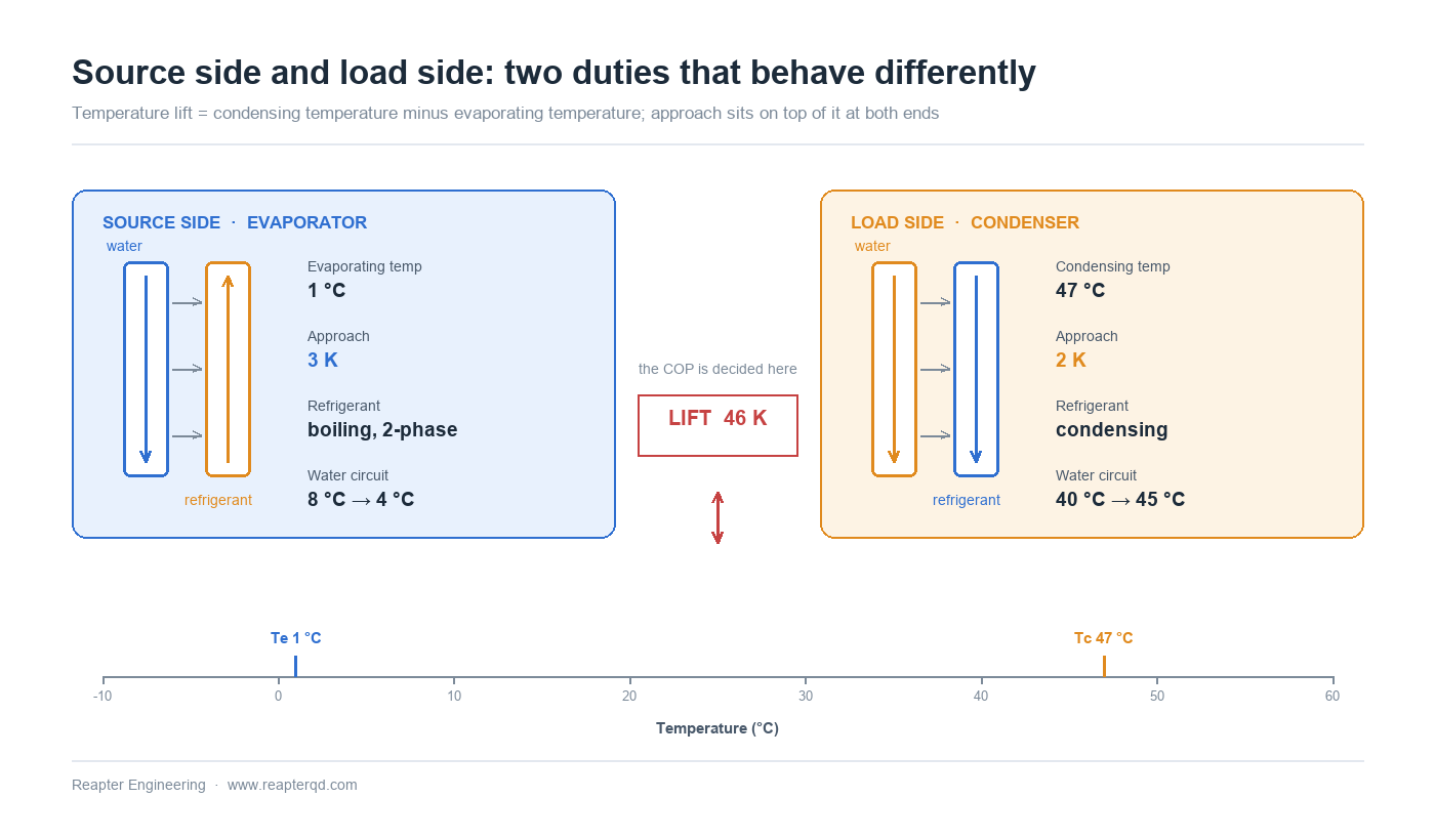
Plate heat exchangers reach low approach because the flow is very close to pure counter-current and the corrugation keeps the boundary layer thin. A well-selected gasketed or brazed unit can hold 1 K; a shell-and-tube of comparable duty typically needs 5 K or more. That is the structural reason plate units dominate hydronic heat pumps rather than a matter of preference.
Refrigerant side: pressure drop costs more than it looks
On the refrigerant side, pressure drop is not merely pump or compressor penalty — it directly shifts the saturation temperature. A 30 kPa drop in the evaporator of an R32 system at low temperature can be worth nearly a kelvin of saturation change, which returns to the lift calculation above. The usual design convention is to hold evaporator refrigerant-side pressure drop below the equivalent of 0.5 K saturation temperature change, and condenser drop below 1 K.
This is where plate geometry matters. Narrow channels and small hydraulic diameter raise the heat transfer coefficient but also raise the pressure drop at a given mass flux. For a heat pump evaporator, the plate pattern and port size should be chosen so that the unit achieves the required approach at an acceptable refrigerant pressure drop — not the highest possible U-value. A very high U-value that costs 1.5 K of saturation is a net loss.
Distribution is the other half of the problem. Refrigerant entering a plate pack must split evenly across every channel; at part load, when mass flow falls well below design, maldistribution shows up as unstable superheat and hunting expansion valves. A distributor designed for the full-load condition alone is a common cause of poor part-load COP.
Water side: pressure drop costs pump energy, every hour
Secondary-side pressure drop is paid continuously by the circulator, so it belongs in the annual energy calculation, not just the datasheet. Typical design values for hydronic heat pump duties fall in the 20–60 kPa range for each exchanger; going below that usually means either larger ports or a wider plate spacing, both of which cost capital.
The more consequential decision is the design temperature difference. A 5 K spread (for example 45/40 °C) halves the flow compared with a 10 K spread and cuts pump energy sharply, but it raises the required plate area and pushes the unit toward a wider, taller frame. Modern low-temperature heating systems increasingly specify 5 K because the distribution losses and pumping energy dominate over the exchanger cost across a 15-year life.
Freeze protection: what glycol actually costs
Air-source units in cold climates and ground-loop systems in freezing ground run a glycol mixture on the source side. Two decisions follow immediately: which glycol, and how much of it.
Ethylene glycol gives slightly better heat transfer and a lower viscosity than propylene glycol at the same concentration, and it is the default for sealed, non-potable circuits. Propylene glycol is chosen where a leak could reach potable water, food or a space where toxicity matters. Both need an inhibitor package maintained over the life of the circuit — depleted inhibitors are a more common cause of corrosion in these loops than the glycol itself.
The thermal penalty is not small. A 30 % ethylene glycol solution has a freezing point around ?15 °C, but compared with water it loses roughly 20–25 % of its convective heat transfer coefficient at the same velocity, gains 20–30 % in pressure drop, and carries about 10 % less heat per unit volume because of the lower specific heat. In sizing terms that generally translates to 10–30 % more plate area for the same duty, with the exact figure depending on concentration and velocity.
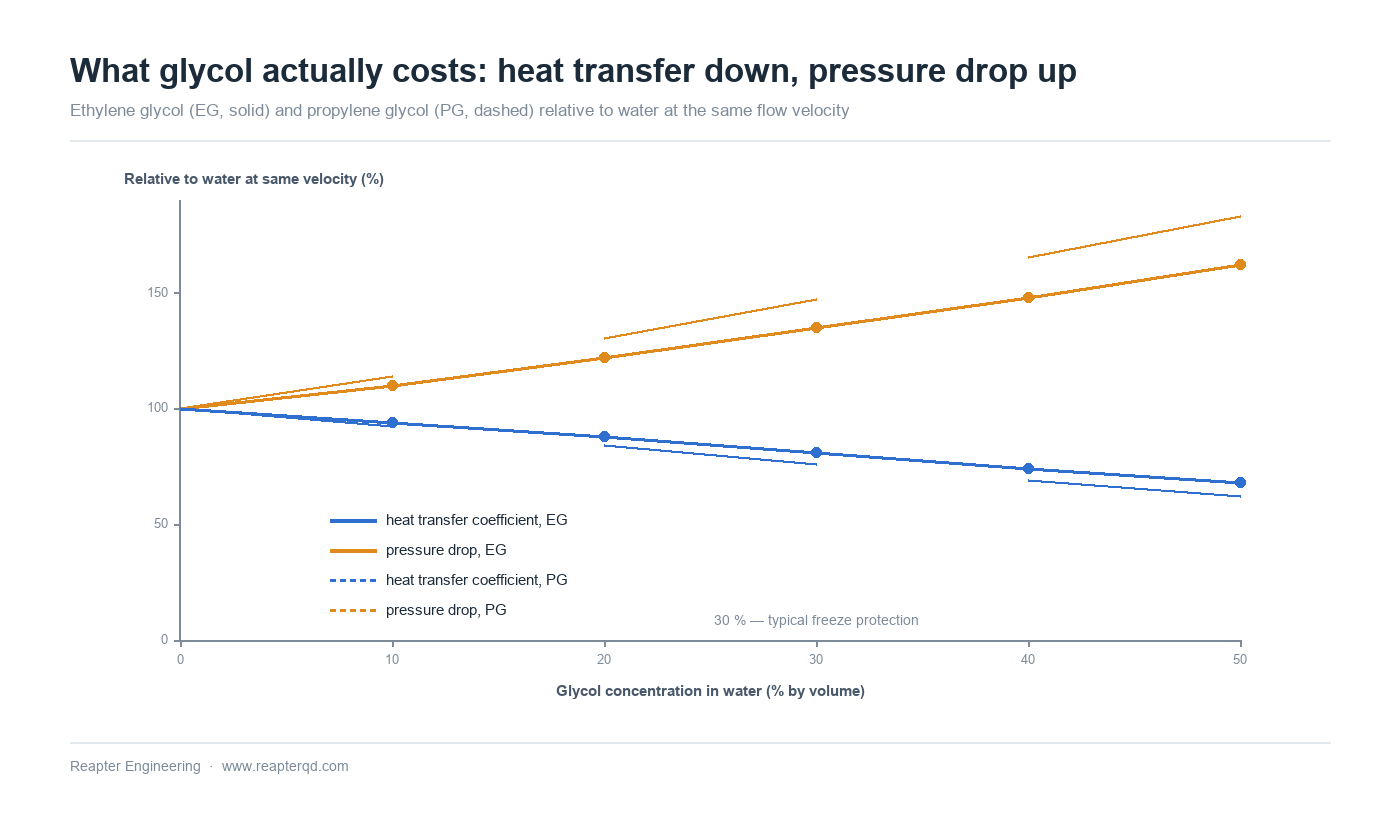
Size the exchanger on the real mixture, not on water. A unit selected for water and then filled with 40 % glycol will not deliver its nominal duty, and the shortfall appears exactly where it hurts most — at the coldest outdoor condition, when the heat pump is already working hardest.
Brazed, semi-welded or gasketed: matching construction to the circuit
Construction choice follows from refrigerant, pressure, and whether either side will ever need mechanical cleaning.
| Construction | Typical heat pump use | Watch out for |
|---|---|---|
| Copper-brazed | Small and mid-capacity unitary and monobloc units; HFC, HFO and R32 circuits | Not repairable; copper is attacked by ammonia; only suitable for clean, closed secondary circuits |
| Semi-welded | Ammonia and CO? systems; duties where the refrigerant side must stay sealed but the water side may need opening | Larger footprint per unit duty; gasket on the service side still needs inspection |
| Gasketed | Larger capacities, open loops, river or well water, anywhere fouling demands access | Elastomer compatibility with the secondary fluid must be checked, not assumed |
| All-welded / shell-and-plate | High pressure, flammable refrigerants with tight charge limits, flooded evaporators | No mechanical cleaning — cleaning must be by chemical circulation |
For ammonia, copper-brazed construction is not an option at all — not for reasons of preference but because ammonia attacks copper and its alloys. Propane and other flammable refrigerants push toward all-welded or semi-welded construction for a different reason: minimizing charge inside the unit reduces the refrigerant quantity that has to be managed under the applicable safety standard.
Where the secondary circuit is open — river water, cooling tower water, well water — a gasketed unit that can be opened for mechanical cleaning will usually outlast a brazed one, even at a higher first cost. For guidance on the material side of that decision, see our article on plate heat exchanger material selection from 316L to Hastelloy.
A practical selection sequence
- Fix the operating envelope first. Source temperature at design cold, flow temperature at design heat, and both at part load. A single design point is not an envelope, and heat pumps spend most hours away from it.
- Choose construction from refrigerant and secondary fluid. Ammonia excludes copper-brazed. Open circuits argue for gasketed. Flammable refrigerants push toward welded.
- Set approach targets per side, not globally. Evaporator 1–2 K, condenser 1–2 K for a modern hydronic unit; relax the condenser first if area must be cut.
- Set pressure drop budgets in saturation terms on the refrigerant side (≤0.5 K evaporator, ≤1 K condenser) and in kPa on the water side (20–60 kPa typical).
- Re-run the duty on the actual glycol mixture, at the lowest expected ambient, before fixing the plate count.
- Check part-load behaviour. Ask for the distributor turndown range and confirm the expansion valve and the plate pack are matched at 30–50 % load, not only at rated capacity.
Two further checks belong on that list for projects with seasonal load profiles: whether the exchanger tolerates reverse operation in defrost, and whether the water side can be drained or is protected by trace heating during a standstill. Our article on variable flow and part-load operation covers the control-side implications.
Common questions
What approach temperature should I specify for a heat pump? For a hydronic heat pump, 1–2 K on both sides is achievable with plate heat exchangers and is where good designs land. Below 1 K the plate area and cost rise steeply for a small COP gain; above 3 K you are leaving measurable energy on the table every hour of operation.
Can a brazed plate heat exchanger be used with ammonia? No. Ammonia attacks copper and copper alloys, so copper-brazed units are excluded. Use semi-welded or all-welded construction with stainless plates.
How much extra area does glycol need? Plan on 10–30 % more plate area than a water-based selection for the same duty, depending on concentration and velocity — 30 % ethylene glycol typically sits around the lower half of that range and 50 % toward the top.
Why does my unit lose capacity in cold weather? Usually two effects together: the source temperature falls, which lowers the evaporating temperature, and if the source circuit is glycol, the mixture's higher viscosity further reduces the heat transfer coefficient. Both were in the design data — but only if the exchanger was sized on the mixture rather than on water.
Is a shell-and-tube acceptable instead? It can be, and for flooded evaporators it is often the standard choice. The trade is approach: shell-and-tube units typically need 5 K or more, which is difficult to reconcile with a high-COP heat pump specification. Our comparison of plate and shell versus shell and tube sets out the boundary.
Conclusion
The heat exchanger is the part of a heat pump where the COP is either protected or quietly given away, and most of the decision is made in four numbers: approach on each side, pressure drop on each side. Get those right on the real fluid at the real cold-day condition and the rest of the specification follows.
Reapter supplies gasketed, brazed and semi-welded plate heat exchangers for heat pump duties, selected against the actual mixture and the full operating envelope rather than a single rated point. If you have a duty to check, send the source and load temperatures, flows, refrigerant and glycol concentration — we will run the selection and show the approach and pressure drop you would get. Request a selection review.
Related information
- Qingdao Ruipute double-wall plate heat exchanger mass production
- 10 characteristics of plate and shell heat exchangers
- The plate heat exchanger manufacturer of the heat exchange station, missed this year, don't miss next year!
- Insiders tell you how to select and replace the gaskets of plate heat exchangers
- Plate heat exchanger manufacturers help HVAC project
- Who says Chinese manufacturing isn't good? Analysis of the manufacture of plate and shell heat exchangers
Relevant article
- Reading a Water Analysis Before You Specify a Plate Heat Exchanger
- High-Temperature Heat Pumps Above 100 °C: Exchanger Selection for Steam Replacement
- Data Centre Waste Heat to District Heating: Matching Low-Grade Heat to a Network
- Plate Heat Exchanger Sizing: A Worked Calculation from Duty to Plate Count
- Plate Heat Exchanger Troubleshooting: Reading the Symptoms Before Opening the Pack
- Winter Shutdown and Freeze Protection for Plate Heat Exchangers
- Transcritical CO2 Systems: Selecting Plate Heat Exchangers for High Pressure
- Waste Heat Recovery with Plate Heat Exchangers: Sizing and Fouling
- Plate Heat Exchangers in Heat Pump Systems: Source-Side and Load-Side Selection
- Plate Heat Exchangers in Data Center Liquid Cooling: CDU Selection
Latest information
- The original lubricant in the chemical plate heat exchanger plays so many roles!
- Heat exchanger station supporting plate heat exchanger or have to pay attention to these points, or easily go wrong
- Heat station supporting plate heat exchanger installation is a technical work, these points should be noted
- Improve the efficiency of industrial boilers with plate heat exchanger, these maintenance points to keep in mind
- The Integrated Heat Exchanger Unit: An Efficient Integration and Intelligent Control Solution for Thermal Energy Conversion
- Sulfuric acid and other corrosive media for industrial plate heat exchanger requirements are what
- Simple and effective chemical cleaning method of coal chemical plate heat exchanger, can effectively improve efficiency
- A high-quality petrochemical plate heat exchanger in the production of what to consider
- These causes of chemical plate heat exchanger gasket aging you may not know
- Chemical plant plate heat exchanger, sulfuric acid cooling needs attention