Free Cooling with Plate Heat Exchangers: Design and Changeover

Open water and clean water never belong in the same circuit
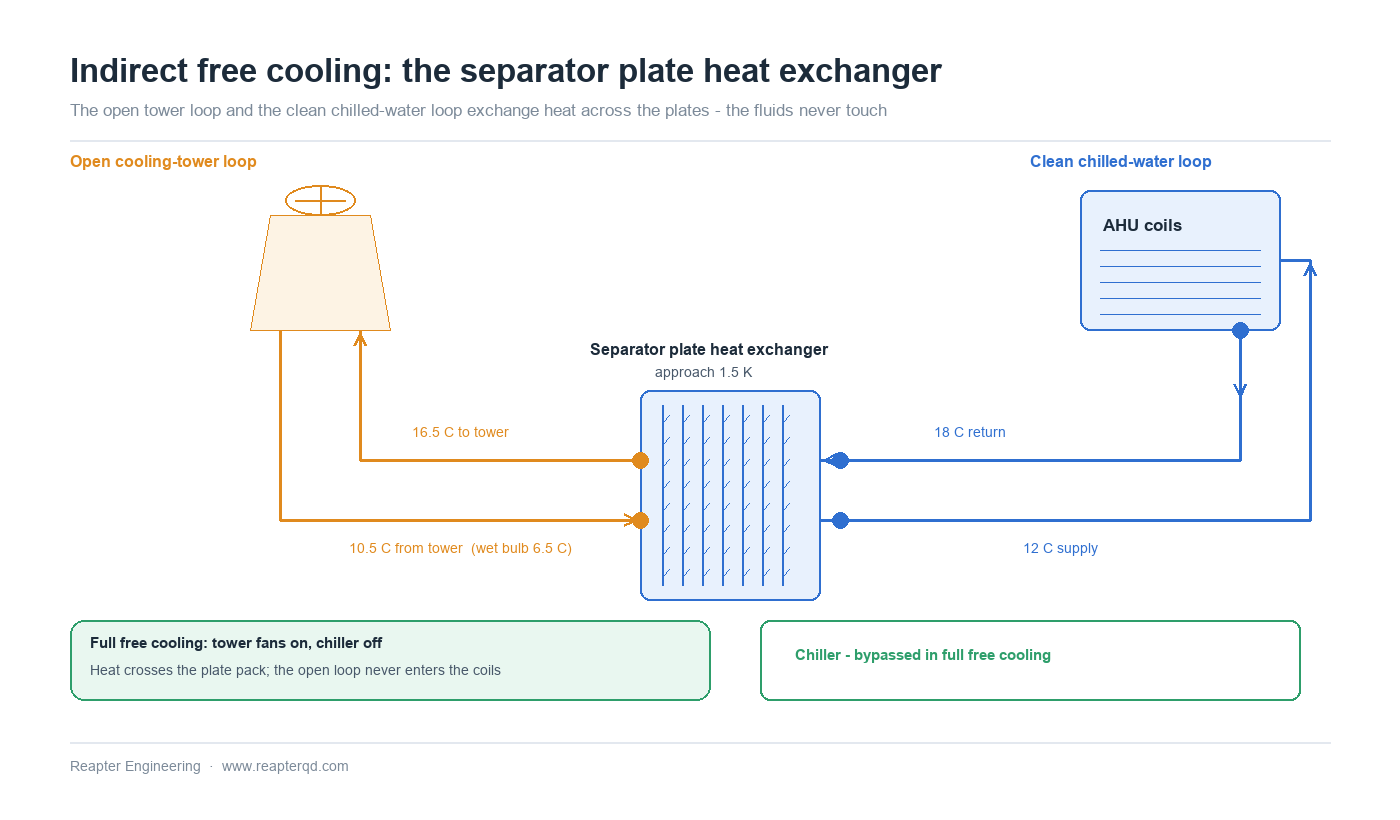
When the weather is cold enough, a chilled-water plant can shed most or all of its compressor load by letting the cooling tower do the chilling. The idea is simple; the plumbing is not. Tower water is open to the atmosphere, loaded with dissolved oxygen, treatment chemicals and airborne dirt, and nobody wants that water inside a hydronic coil circuit. Indirect free cooling - often called a waterside economizer - solves this with a separator heat exchanger: the tower loop and the chilled-water loop exchange heat across plates but never mix. A gasketed plate heat exchanger is the usual choice because a close approach (1-2 K is routine) directly raises the ambient temperature at which free cooling becomes possible, and every kelvin there is worth hours of compressor-off operation each year.
What the separator exchanger actually does
The separator sits between two loops with very different characters. On the tower side: open to atmosphere, 30-60 °C in summer, near freezing in winter, carrying biocides, scale inhibitors and whatever the wind delivers. On the chilled-water side: closed, clean, and feeding coils and chillers that tolerate neither dirt nor drain-down. Counter-current flow through the chevron plate pack lets the two streams approach each other within 1-2 K, against roughly 3-5 K for a shell-and-tube separator of comparable duty. That difference is not cosmetic - it moves the whole changeover temperature, which is the single number that decides how many free-cooling hours a climate delivers.
Stacking the approaches: where the changeover temperature comes from
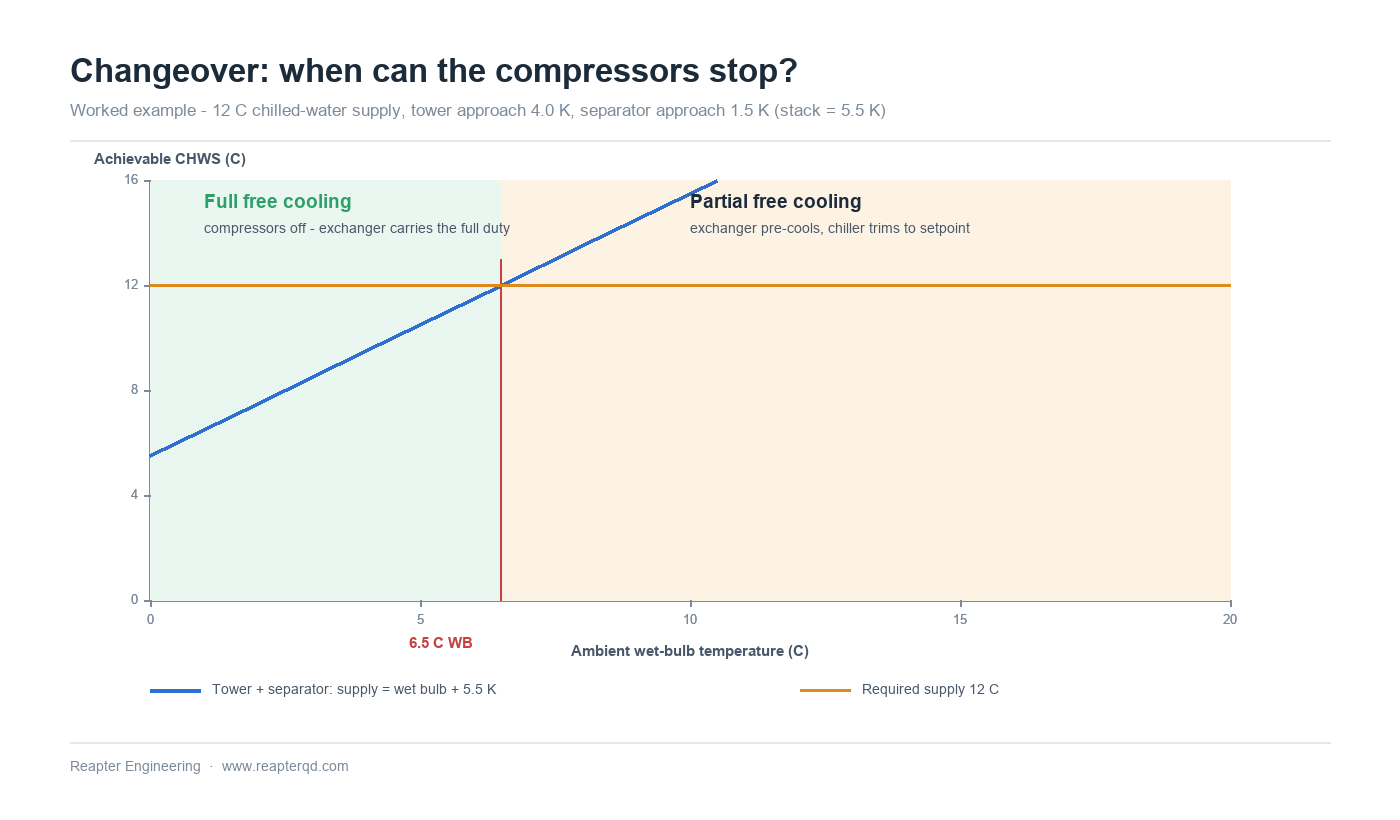
The changeover point is a chain of margins, not a single property. Working backwards from the required chilled-water supply temperature:
- Tower approach - leaving tower water sits 3-5 K above ambient wet-bulb at design flow (4.0 K in this example).
- Separator approach - the plate heat exchanger adds 1-2 K between tower water and chilled water (1.5 K here).
- Control margin - a practical changeover setpoint sits a little below the theoretical value so the plant does not hunt across the threshold.
With a 12 °C supply setpoint, the stack is 4.0 + 1.5 = 5.5 K, so full free cooling becomes available at about a 6.5 °C wet bulb. In maritime climates wet-bulb and dry-bulb track closely; in dry continental climates the dry-bulb changeover temperature can sit several kelvin higher, which is why the free-cooling hour count must be built from local wet-bulb bin data rather than dry-bulb averages. A drier site is usually a better free-cooling site than its dry-bulb temperature alone suggests.
Partial free cooling: chiller and exchanger in series
Above the full changeover wet-bulb there is a long band of weather where the tower cannot carry the whole load but can carry part of it. This is the most economically interesting regime. The separator cools the return water as far as the ambient allows, and the chiller - in series, downstream - trims the remaining kelvin to setpoint. Compressor power falls roughly in proportion to the load removed, so even 2-3 K of pre-cooling is visible on the energy bill. Control is straightforward: modulate the tower fans to hold the lowest practical tower leaving temperature, and float the chiller setpoint to the separator's achievable supply plus a small margin. Below the changeover wet-bulb, isolate the chiller completely and let the exchanger carry the full duty.
Sizing one exchanger for two different duties
The separator often has to work at its hardest exactly when the chiller is off: full building load, no mechanical backup, and a design approach of 1.5 K or less. That low-approach, high-flow case - not the partial-duty case - sizes the plate pack. Size it at the binding condition (full free-cooling load at target approach), then check the same plate count against partial-duty operation for pressure drop and control stability. Extra plates beyond the binding case buy approach you cannot use and add cost and hold-up volume; too few plates push the changeover wet-bulb down and quietly delete free-cooling hours.
Where the exchanger sits: four configurations
| Configuration | How it works | Where it fits | Watch-outs |
|---|---|---|---|
| Exchanger + chiller in series (exchanger first) | Tower water pre-cools the return; chiller trims to setpoint | The partial free-cooling workhorse; maximum kWh saved per year | Chiller sees warmer entering water at high ambient - check its operating envelope |
| Exchanger + chiller in parallel | Flow splits between the two paths | Retrofit plants where series piping is impractical | Balancing is fussier; neither path runs at its best point |
| Exchanger only, full changeover | Chiller fully isolated below the changeover wet-bulb | Cold climates with long compressor-off seasons | Exchanger carries full duty alone - size it for that, with no mechanical backup |
| Dry cooler instead of tower | Same separator logic, closed dry cooler on the hot side | Water-scarce or freezing sites | Changeover decided on dry-bulb; dry-bulb approach is wider than wet-bulb, so hours differ |
Cold climates, water quality and seasonal details
On the tower side, freeze protection follows the usual rules: glycol where the loop can idle in sub-zero weather (accepted as a modest tower capacity derate), heat-traced or drained exposed piping, and a circulation discipline for cold snaps. The separator makes this easy - the clean loop can stay glycol-free while only the small open loop carries the antifreeze penalty. On water quality, remember that the plate channels are narrow: a strainer ahead of the exchanger, conductivity-controlled blowdown and side-stream filtration on the tower loop keep the pack open for years. Where the tower loop runs on seawater or brackish water - a frequent arrangement for coastal plants - titanium plates are the standard answer, and the clean loop keeps its normal 316L hardware.
Common questions
Why not run tower water straight to the coils and skip the exchanger? Direct free cooling saves the approach penalty but puts open-loop water - oxygen, solids, treatment chemicals - into every coil, and drains the tower into the building's water budget each time the system breathes. For most plants the 1-2 K approach of a plate separator is a small price for a closed, clean, corrosion-free chilled circuit.
How much is one kelvin of approach worth? One kelvin less stack moves the changeover wet-bulb up by one kelvin, which in temperate climates typically adds a meaningful block of compressor-off hours in spring and autumn. The honest answer comes from the local wet-bulb bin data: recompute the hour count at 4.5 K and 5.5 K stack and compare - the difference is usually worth more than the marginal plate cost.
Can the same plate pack serve the mechanical-cooling season too? Often yes - in series plants the separator stays in the return line year-round. Size the pack at the free-cooling binding case, then verify pressure drop and part-load behaviour for the rest of the year. If the mechanical-season duty is extreme, a dedicated bypass keeps the exchanger out of the high-summer flow path.
Does this work with a dry cooler instead of a cooling tower? Yes - the separator logic is identical. The changeover decision moves to dry-bulb, and because a dry cooler's approach to dry-bulb is wider than a tower's approach to wet-bulb, the changeover temperature is higher; the saving in water and winterisation often compensates in the right climate.
Conclusion
Indirect free cooling is one of the clearest cases where a plate heat exchanger's close approach converts directly into operating money: every kelvin saved at the separator raises the changeover temperature and lengthens the compressor-off season. Reapter supplies gasketed plate heat exchangers for waterside-economizer duties and manufactures replacement plates and gaskets compatible with the major installed frame brands, with engineering support and spare-parts supply for projects worldwide. If you are adding a waterside economizer to an existing plant and want the separator duty checked - or a replacement pack quoted against your current frame - contact us with your flows, temperatures and climate data.
Related information
- The application of plate and shell heat exchanger in power plant flue gas recovery
- How to quote the heating plate heat exchanger? A more economical and suitable plate heat exchanger must meet these conditions
- Plate heat exchangers in paper mills can kill three birds with one stone only because of this feature
- What is the key to the manufacture of plate heat exchangers with small temperature differences?
- Causes of corrosion of heat exchanger plates
- Coal chemical plate heat exchanger in the selection process of these places to pay attention to
Relevant article
- Plate Heat Exchanger Connections: DN vs NPS, PN vs Class, and What Goes Wrong on Site
- Free Cooling with Plate Heat Exchangers: Design and Changeover
- Multi-Section Plate Heat Exchangers: Two Duties, One Frame
- Retrofitting a Shell-and-Tube with a Plate Heat Exchanger: Fitting the Duty into an Existing Plant
- Packing a Plate Heat Exchanger for Ocean Freight: Preservation, Storage and Site Handover
- Plate Heat Exchangers Under Vacuum: Operating on the Negative-Pressure Side
- Gasket Compression Set and Bolt Torque Management in Plate Heat Exchangers
- Parallel Plate Heat Exchanger Banks: N+1 Redundancy and Flow Balancing
- Reading a Water Analysis Before You Specify a Plate Heat Exchanger
- High-Temperature Heat Pumps Above 100 °C: Exchanger Selection for Steam Replacement
Latest information
- The original lubricant in the chemical plate heat exchanger plays so many roles!
- Heat exchanger station supporting plate heat exchanger or have to pay attention to these points, or easily go wrong
- Heat station supporting plate heat exchanger installation is a technical work, these points should be noted
- Improve the efficiency of industrial boilers with plate heat exchanger, these maintenance points to keep in mind
- The Integrated Heat Exchanger Unit: An Efficient Integration and Intelligent Control Solution for Thermal Energy Conversion
- Sulfuric acid and other corrosive media for industrial plate heat exchanger requirements are what
- Simple and effective chemical cleaning method of coal chemical plate heat exchanger, can effectively improve efficiency
- A high-quality petrochemical plate heat exchanger in the production of what to consider
- These causes of chemical plate heat exchanger gasket aging you may not know
- Chemical plant plate heat exchanger, sulfuric acid cooling needs attention