Retrofitting a Shell-and-Tube with a Plate Heat Exchanger: Fitting the Duty into an Existing Plant

The thermal duty is usually the easy part
A shell-and-tube exchanger that has served a plant for fifteen years is normally oversized, fouled, or both. Replacing it with a gasketed plate unit of the same duty is therefore straightforward on paper: the plate pack needs a fraction of the surface, because the overall coefficient for water-to-water duty is three to five times higher. What decides whether the retrofit succeeds sits around the duty rather than inside it — the pressure drop the existing pump can still spare, the distance between the existing flanges, the standard those flanges are drilled to, the route the new unit takes through the door, and the hours the plant can be offline. Projects fail on those constraints, not on the heat balance.
Read the old unit before sizing the new one
Nameplate data records what was bought, not what the unit is doing today. Two surprises are common: the real duty has drifted 15 to 25 percent below nameplate because the process was downrated, and the real flow is higher than design because a pump was replaced at some point. Both change the plate count, and neither appears on the tag.
Five things are worth recording on site:
- Measured flows and temperatures at the current operating point — from the historian, or a clamp-on ultrasonic meter. Nameplate values are a starting point, not an answer.
- Actual pressure drop across each side. It is rarely instrumented and it is the most useful number in the exercise: a fouled shell-and-tube can show 150 kPa where the clean design was 40, and the pump has been trimmed to live with it.
- Water quality on both sides — chlorides, hardness, suspended solids, and whether each loop is open or closed.
- Duty profile: continuous, batch or seasonal, and how often the unit starts.
- What the process needs in approach temperature, not what the old unit happened to deliver.
The last item matters more than it looks. A shell-and-tube achieving an 8 °C approach is often written into a replacement specification as though 8 °C were a process requirement, when 4 °C would be accepted — and a smaller, cheaper pack results.
Why the same duty fits in a fifth of the floor
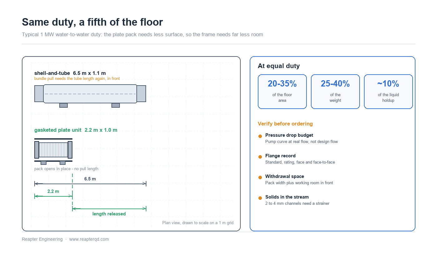
The corrugated plate pack reaches turbulent flow at Reynolds numbers where a bare tube bundle is still in transition. Channels are 2 to 4 mm deep, so the hydraulic diameter is small and the wall shear is high; coefficients of 3000 to 6000 W/m2K are ordinary for water, against 500 to 1200 for a clean shell-and-tube. Higher coefficient means less surface, and less surface in this geometry means a much smaller frame: typically 20 to 35 percent of the floor area and 25 to 40 percent of the weight at equal duty.
A second effect is easy to overlook and often worth more than the space: liquid holdup falls by roughly an order of magnitude. A plate unit holds tens of litres where the shell held several hundred, which shortens response time and cuts the volume of treatment chemicals and of drain-down.
Shrinking the surface carries one trap. A shell-and-tube with 20 percent spare surface costs little to build; a plate pack with 20 percent spare surface costs one plate in five, which also costs little — but a pack sized with no margin will foul into a shortfall within a season, and the first symptom is not a dirty unit but a duty that cannot be met at design flow. Size the clean coefficient honestly, then add the fouling allowance as extra plates.
Four constraints decide whether the swap is feasible
Assuming the duty fits, four boundary conditions decide whether the unit can be installed and whether it will behave. Check them before the pack is sized, because each one can change the selection.
- Available pressure drop. This is the binding constraint on most retrofits. The pack pays for its high coefficient with more pressure drop per unit area, and the pump curve is fixed. Compare the required drop at the real flow with the head the pump produces at that flow — not at the design point. If the margin is thin, the answers are a larger port, a wider channel, fewer passes, or a larger pack at lower velocity; all cost surface, which is still cheaper than a new pump.
- Nozzle size and velocity. Liquid velocities of 2 to 3 m/s in the ports are conventional. A 150 mm line into a 100 mm port needs a reducer and adds pressure drop; more often the port matches the pipe, so the connecting spool is a straight flange-to-flange piece.
- Flange standard, rating and face. An ANSI 150 flange does not bolt to an EN 1092-1 PN16 flange, and a raised face does not seal against a flat face. Where the connections differ, the answer is a transition spool carrying the two standards on its ends — cheap to make, and the reason a unit ordered without that information arrives with joints nobody can close.
- Space, withdrawal and lifting. The frame needs clear space in front of the movable cover for the pack to open, plus room to withdraw a tie bar end to end. The lifting route and door width decide whether a skidded unit enters at all. The unit is lighter, but its load concentrates on four small feet, so check the plinth for point loading rather than total weight.
| Parameter | Existing shell-and-tube | Gasketed PHE at the same duty | What to verify |
|---|---|---|---|
| Overall coefficient, water to water | 500 to 1200 W/m2K | 3000 to 6000 W/m2K | Clean basis, then fouling allowance as extra plates |
| Floor area | Baseline | Typically 20 to 35 percent | Measure the free space, not the drawing |
| Weight | Baseline | Typically 25 to 40 percent | Point loading on the existing plinth, lifting route |
| Liquid holdup | Several hundred litres | Tens of litres | Control tuning, drain volume, chemical dose |
| Practical approach temperature | 5 to 10 °C | 1 to 2 °C | Only pay for approach the process actually needs |
| Pressure drop per side | Often 30 to 70 kPa | 50 to 100 kPa at conventional velocities | Pump curve at real flow, in the fouled condition |
| Cleaning | Bundle pull, or chemical in place | Pack opened in place, CIP possible | Clearance in front of the cover |
| Solids tolerance | Moderate, tubes are 10 to 20 mm | Low, channels are 2 to 4 mm | Strainer, or a wide-gap plate pattern |
| Design pressure | High | 16 bar standard, 25 bar on special frames | Design and test pressure on the nameplate |
| Temperature limit | Set by materials | Set by the gasket: NBR near 110 °C, EPDM near 150 °C | Continuous temperature, not excursions |
Where a plate pack is the wrong answer
A gasketed plate unit is a poor fit in five situations, and in each the alternative is a different exchanger, not a bigger one:
- Fibrous or coarse solids. Channels of 2 to 4 mm block. Paper stock, slurry, crystallising solutions and cooling water carrying shell debris will blind a pack in weeks.
- Design pressure above roughly 16 bar. A welded or semi-welded unit, or the existing shell, is the sensible answer.
- Continuous temperature above the gasket limit. NBR is comfortable to about 110 °C and EPDM to about 150 °C; above that, welded units.
- Very large flow with almost no pressure drop available, as with gravity flow or a low-head circulating pump.
- Frequent wide thermal cycling on a tight maintenance budget. Gaskets tolerate cycling, but every cycle consumes life.
The site work: spools, strainers and changeover
Most of the risk in a retrofit is in the pipework, and most of it is avoidable at the drawing stage.
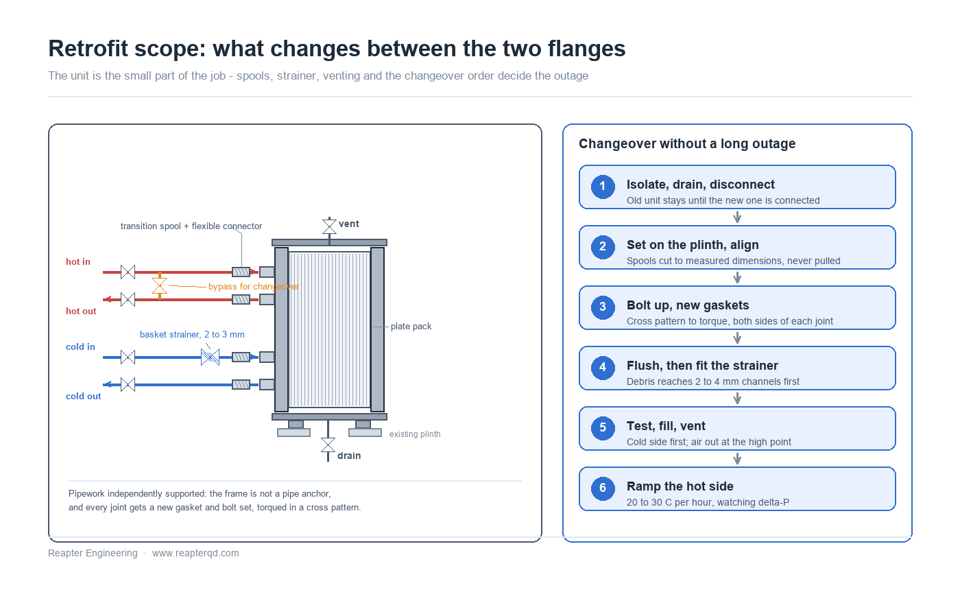
- Never pull the pipe to the unit. The frame is not a pipe anchor. Spools cut to measured dimensions bring the flanges to the nozzles, and flexible connectors take up thermal movement. Bolting a misaligned flange shut loads the pack unevenly and produces a leak no torque value will fix.
- Strainer on the dirty side, upstream, with a differential gauge. A basket with 2 to 3 mm perforations protects the channels; the gauge says when it needs cleaning, before the duty drops.
- Vent at the high point, drain at the low point. A pack is a set of vertical blind passages. Air trapped at the top removes surface from service and appears as a duty shortfall, not an alarm.
- A gauge or differential transmitter across each side. The pressure drop trend is the cheapest fouling indicator available, and the first evidence when a performance complaint arrives.
A sequence that keeps the plant running
The work fits inside a normal shutdown if the preparation happened beforehand:
- Confirm the flange record. Standard, rating, face type, bolt circle and measured face-to-face distance — photographed with a tape across the joint.
- Prefabricate the spools and the bypass from measured dimensions, not from the drawing. Cut, weld, test and paint before the shutdown.
- Isolate, drain, disconnect. Keep the old unit intact until the new one is connected — it is the fallback if a spool does not fit.
- Set the unit, then align the pipe. Shim the feet, check the frame is vertical, bring the spools to the nozzles, and torque in a cross pattern with new gaskets on both sides of every joint.
- Flush the pipework before the pack sees it. Debris reaches the channels first: flush through a temporary bypass, then fit the strainer basket.
- Test, fill, vent. Pressure test at the specified value, fill slowly, vent the high point, and pressurise the cold side first.
- Ramp the hot side at 20 to 30 °C per hour, watching differential pressure and approach.
- Retune the control loop. With a tenth of the holdup the same settings will overshoot; shorten the integral time and check valve authority.
What a supplier needs before quoting
Almost every failed retrofit quotation traces back to a missing measurement, and nearly all of them can be captured in one visit with a tape, a camera and a marked-up drawing: the P&ID, the measured duty with its date, the water analysis for both sides, the four flange records, a plan and elevation sketch with dimensions to the nearest wall and pipe, the lifting route and door width, and the applicable design code and documentation language.
For a project on the other side of the world, that record is the basis of the order. With it, the unit, the transition spools, the strainer and the spares are built as one lot, tested together and shipped in one crate — instead of the unit arriving first and the spools being fabricated on site from a drawing nobody checked.
Common questions
Can the existing pump be kept? Usually yes, if the available pressure drop is checked before the pack is sized. Size to the pump's real curve at the real flow, and accept a larger frame at lower velocity if the margin is small. Replacing a pump is a bigger project than adding plates.
Does a plate unit need more maintenance space? A different kind. The bundle pull needs the tube length again in front of the channel; the plate unit needs roughly the pack width plus working room in front of the cover, which is usually less. Measure both before assuming the footprint gain becomes free floor.
Will the same design pressure be available? Standard gasketed frames are rated to 16 bar and special frames to around 25 bar. If the existing shell is rated higher, do not force the swap — a semi-welded or welded unit keeps the plate geometry and raises the limit, at a cost in cleanability.
What changes for the control system? Less holdup means a faster response and less damping. The temperature loop will need retuning, and a control valve sized on the old pressure drop may now be oversized.
Conclusion
A shell-and-tube to plate retrofit is a piping project with a heat exchanger in the middle. The thermal selection is the quick part; the pressure drop budget, the flange record, the withdrawal space and the solids in the stream decide whether the unit works in that position. Get those four right and the same duty runs in a fifth of the floor with a tenth of the water in it.
Reapter builds gasketed plate heat exchangers for replacement duty and supplies them with transition spools, strainers and spares as one delivery for projects overseas. If you are replacing an existing shell-and-tube, send us the measured duty, the flange record and a photograph of the space — we will come back with a selection and the piping scope that goes with it.
Related information
- How to choose the right plate heat exchanger
- On Double Eleven, Xiaomi invested 1 billion in subsidies to release a new machine. The plate heat exchanger can achieve such an extreme price-performa
- Do you know how to solve the problem that the heating plate heat exchanger cannot reach the preset temperature?
- Plate heat exchanger plate quality requirements
- Industrial plate heat exchanger frame plate plate treatment process, how much do you know
- Waste heat recovery plate heat exchanger has many features, do you know which ones?
Relevant article
- Plate Heat Exchanger Connections: DN vs NPS, PN vs Class, and What Goes Wrong on Site
- Free Cooling with Plate Heat Exchangers: Design and Changeover
- Multi-Section Plate Heat Exchangers: Two Duties, One Frame
- Retrofitting a Shell-and-Tube with a Plate Heat Exchanger: Fitting the Duty into an Existing Plant
- Packing a Plate Heat Exchanger for Ocean Freight: Preservation, Storage and Site Handover
- Plate Heat Exchangers Under Vacuum: Operating on the Negative-Pressure Side
- Gasket Compression Set and Bolt Torque Management in Plate Heat Exchangers
- Parallel Plate Heat Exchanger Banks: N+1 Redundancy and Flow Balancing
- Reading a Water Analysis Before You Specify a Plate Heat Exchanger
- High-Temperature Heat Pumps Above 100 °C: Exchanger Selection for Steam Replacement
Latest information
- The original lubricant in the chemical plate heat exchanger plays so many roles!
- Heat exchanger station supporting plate heat exchanger or have to pay attention to these points, or easily go wrong
- Heat station supporting plate heat exchanger installation is a technical work, these points should be noted
- Improve the efficiency of industrial boilers with plate heat exchanger, these maintenance points to keep in mind
- The Integrated Heat Exchanger Unit: An Efficient Integration and Intelligent Control Solution for Thermal Energy Conversion
- Sulfuric acid and other corrosive media for industrial plate heat exchanger requirements are what
- Simple and effective chemical cleaning method of coal chemical plate heat exchanger, can effectively improve efficiency
- A high-quality petrochemical plate heat exchanger in the production of what to consider
- These causes of chemical plate heat exchanger gasket aging you may not know
- Chemical plant plate heat exchanger, sulfuric acid cooling needs attention